

Looking for a digital isolator IC
 Don M
Posts: 1,654
Don M
Posts: 1,654
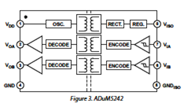
I am looking for an isolator IC similar to the Analog Devices ADUM5242. What is nice about this IC is that it can operate from a single supply. But that is also the problem. It only works at 5VDC. I need one that will work at 3.3VDC to use with a Prop circuit as I don't have 5VDC available.
Here's some details:
1. The output side of the isolator will be connected to the Prop 3.3VDC logic
2. The input side of the isolator will be connected to an isolated buss that is 5VDC logic but no steady 5VDC supply available.
3. Really only need 1 channel
If anyone knows of another device that fits the bill or has an alternate suggestion let me know. An optoisolator will not work as it will draw too much current from the buss.
Thanks.
Don

640 x 372 - 114K
Comments
Could you use an optoisolator if you also added a logic buffer ahead of it? Also, take a look at TI's ISO721.
-Phil
-Phil
I've used the ADUM2250 to make an isolated i2c bus, and it too is specified to provide isolation at 3.3 V.
On this particular project it turns out I will have access to 5VDC from the USB port. I have attached a partial schematic for reference. I think this should work. The XNOR gate is at 3.3VDC hence the resistive voltage divider going into it from the isolator. Any comments?
Edit: I updated the drawing
Hey, ADI, nice to know you are out there. I may be looking at some ADI devices (A/D DAC 1-10Ms/s range) though mostly learning to use them with the prop. I have seen these chips as well as some similar from TI, the AVNET eNewsletter is a very nice resource (its free y'all) and the FAEs I have talked to are great resources as well. Any possibility of sampling these devices? Probably Don would be interested in getting a couple to try in his development, and myself down the road if I ever get a grant to develop a semi invasive medical device. I am not sure of ADI's sample policies, TI seems even with the National merger, to be very liberal in their samples programs as well.
Frank Freedman, AAS, CRES
My application of the ADUM2250 is for isolated i2c with an ADC for a pH sensor, also for isolated 4-20mA. It uses a separate DC-DC to provide isolated 12V for the loop.
Don M - I'm going to ask one our very capable applications engineers to hop on and assist you.
Tracy, Frank - when you are ready, let me know what you need and I'll help out. Keep in mind I am only responsible for our iCoupler products (beginning with ADuM)
Thanks...........
I am the ADI applications engineer that supports the isoPower devices.
I looked over your application and schematics. First, your question about the input voltage tolerance when running at 3.3V. The ADuM5202 uses standard CMOS structure in its logic inputs, in particular it has ESD protection diodes that connect to VDD and GND. When the input level is more than 1 diode drop above the VDD level, then it will forward bias one of these diodes. They are built to disipate ESD transients, but not continuous power, so they can be damaged by continuously running them with forward bias. If damage occurs, it might not effect functionality, but you might eventually find that the ESD protection is gone. My rule of thumb is limit the current to less than 1mA and you should be ok, but it might slow the input down.
I am a little puzzled why you are buffering the signals with optocouplers when the ADuM5202 has isolated channels. I may not have the big picture here, but it seems like since you have 3.3V available on each side, if you use the ADuM5201 you could just use the data channels directly.
You input would have great value here, and generate some sales to boot!
Dealing with 4-20mA loops is always challenging. What do you have going on with the ADuM2250?
@MSCantrell, I'm attaching a schematic of my ADuM2250 circuit. This was originally made for the BASIC Stamp 2pe (OWL2pe data logger), but I'd like at some point in time to modify it for the Propeller.
On one side is the µC and on the other side are two channels of 16 bit ADC, using the ADS1100. One of those goes to a bridge sensor (Druck level meter) and the other to a 4-20mA device, both having to do with hydrology and cables that extend quite a distance to the measurement point, especially the 4-20mA. The system power is 12V, and a separate 1W isolated DC-DC module provides isolated 12V for the ADC side of the ADuM225 and for the 4-20mA loop.
The thing that puzzled me at the time, and I still wonder if I got it right, is this statement from the data sheet, regarding the difference between side 1 and side 2:
Because the Side 1 pin has a modified output level/input threshold, Side 1 of the ADuM2250/ADuM2251 can only communicate with devices fully compliant with the I2C standard. In other words, Side 2 of the ADuM2250/ADuM2251 is I2C-compliant while Side 1 is only I2C-compatible.
The Side 1 I/O pins must not be connected to other I2C buffers that implement a similar scheme of dual I/O threshold detection. This latch-up prevention scheme is implemented in several popular I2C level shifting and bus extension products currently available from Analog Devices and other manufacturers.
Most of the examples in the data sheet assume that one is creating an isolated i2c buss, and therefore side 1 connects to the MCU and side 2 connects to the isolated buss where these other isolation devices may be present. In this case, I wanted to connect possibly several of these devices to one MCU i2c buss on the non-isolated side, so I have side 2 to the MCU and side 1 to the isolated ADCs. Is that a common way to do it, or have I misinterpreted the caution? Why is it not possible to make one that is perfectly symmetric?
Side 2 has big high power buffers that can drive large capacitive loads, so that side is best to drive long cables.
Mark
So 400pF, so that would be about 4 meters of cable or a fanout to N? devices on a buss. For my apps, the ADuM2250 and its wiring on both sides is short, close to the µP.
The figure in the data sheet that shows the typical interface does not indicate a buss topology as such.
Here is how I imagine it, and I wonder if this agrees with what the designers and FAEs have in mind.
The CPU (in our case that would be the BASIC Stamp or the Propeller), has an i2c buss that talks to side 2 of several ADuM2250s, and each of those has a i2c sensor or device or another i2c peripheral µP on its side 1. Each of those then can have its own common mode fluctuations for isolation of say, an pH or water quality sensor or 4-20 loop, and each has its own resistance to ESD events that might take out one node without damaging the others. One isolator might have multiple i2c devices on its peripheral side 1, but all of those would be subject to the same common mode interference and ESD exposure, and all of them would have to be fully i2c compliant.
Is this a "typical" picture for deployment of the ADuM2250?
MSCantrell- This is being used as an add-on to an existing device that already contains the opto-couplers. Those I can't change. I am devising an add-on circuit consisting only of the ADUM device and the XNOR IC along with any needed resistors / capacitors. The existing device operates from the USB power supply at 5VDC but is regulated down to 3.3VDC to supply the IC's on the device. I don't have access to ANY supply voltage on the isolated side of the buss. The isolated side of the buss needs to work with either 0-3.3VDC or 0-5VDC logic levels.