PROJECT: Automatic Transmission Interface board (part 1 of 3)
I have a highly modified 1994 Toyota Supra as you can see in the pictures below.
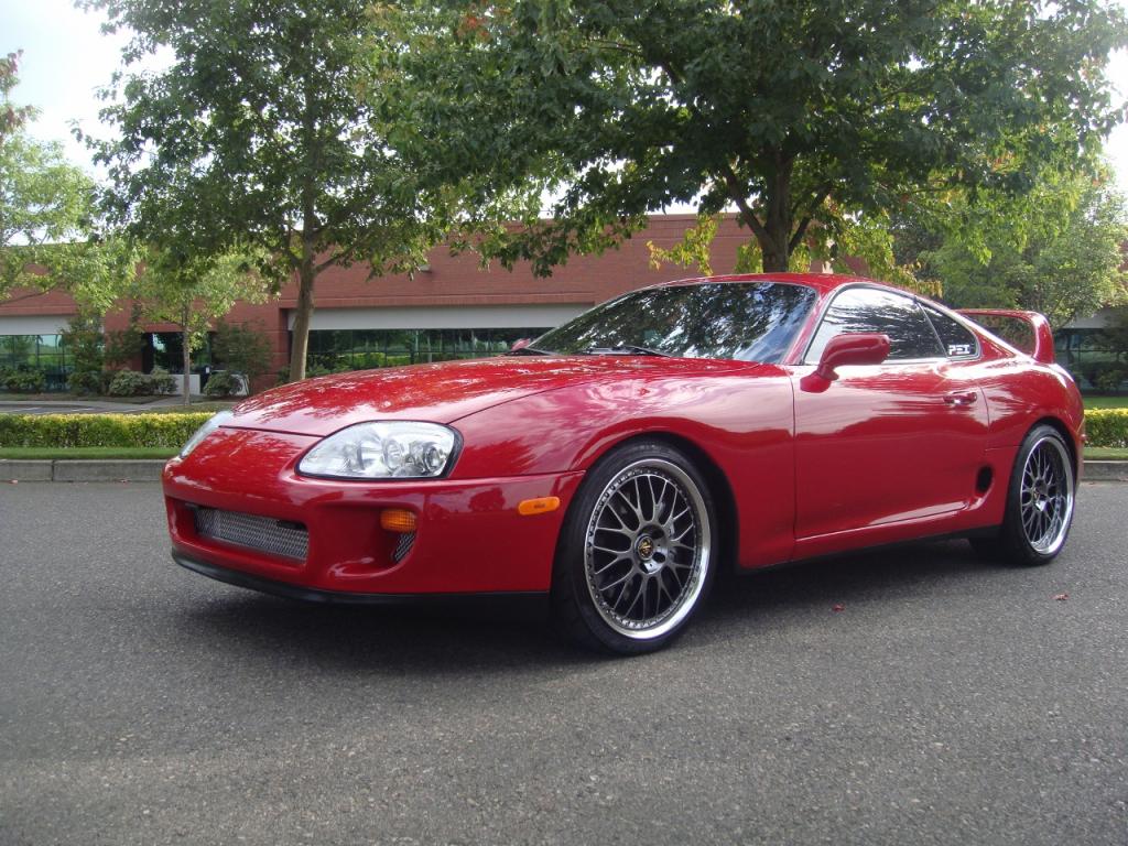

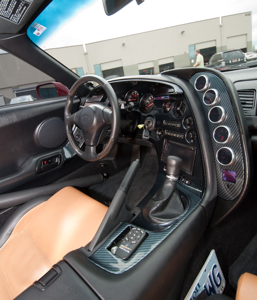
I have had this car for about 10 years now and during that time managed to break the stock automatic transmission (Toyota A340E) three times due to the power level I am at (~900 crank HP). Several years ago I decided to fix that problem once and for all by changing the transmission over to a GM 4L80E, which is a heavy duty transmission that GM used in its trucks. Both the A340E and 4L80E transmissions are 4 speeds with an overdrive gear. We got the GM 4L80E to work pretty well but I wanted to go a step further and make the transmission install look like it was completely stock. This means mainly 2 things. First, that the dash light indicators for the automatic range would reflect exactly the range position selected by the ratchet shifter for the 4L80E transmission. Second, I have an aftermarket ECU in the car and I wanted to make the transmission and its operation look to the ECU like it was controlling the stock A340E transmission. There are some subtle differences that require an electronic solution to fully address.
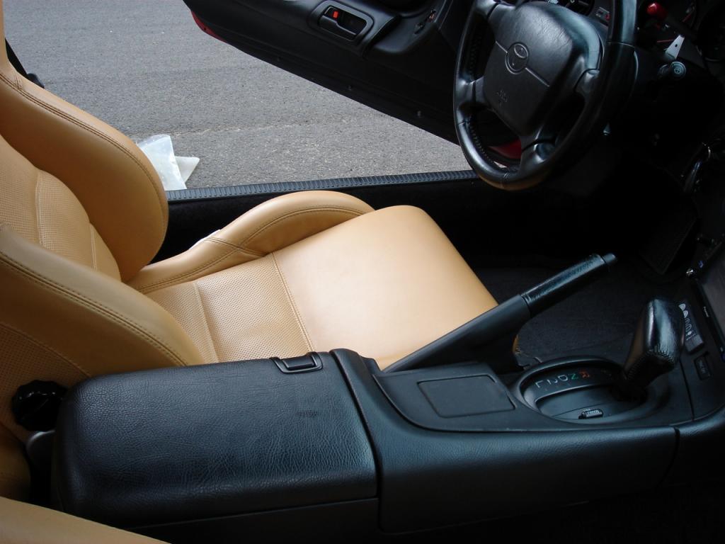
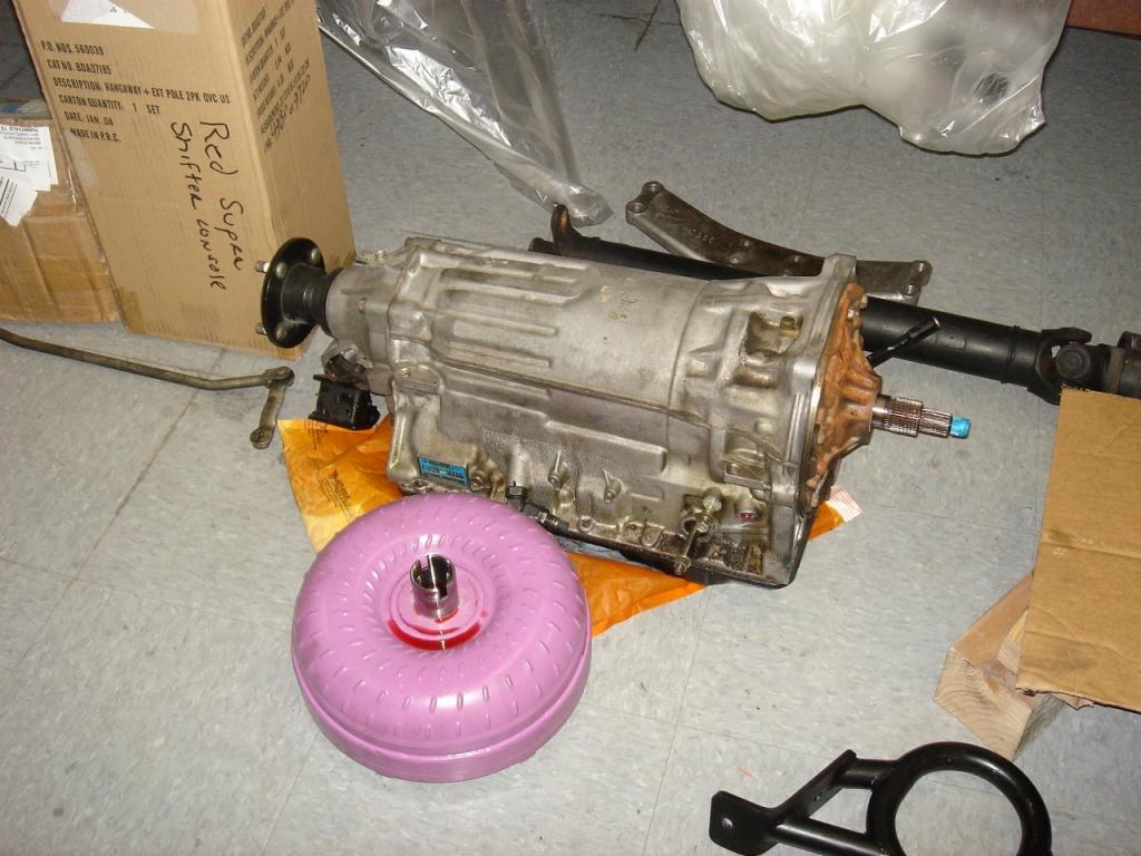
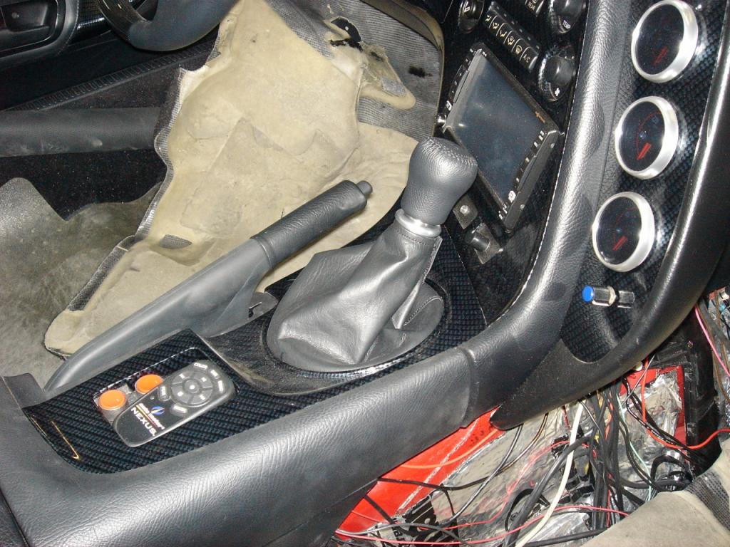
The stock A340E transmission has a floor shifter that allows you to select between 3 forward gear positions (D, 2, 1) and it has a button on the shifter to turn overdrive on/off and another button to select between fully automatic shift mode (ECU fully drives shifting and forward gear selection) and a sport manual shift mode (user shifts and makes all forward gear selections). The pictures below shows the stock floor shifter and the A340E transmission.
The actual range position selected by the stock floor shifter drives a mechanical gear selector indicator on the transmission. This mechanical gear selector is like a multi-way switch that separately indicates +12V or OFF for the R, P, N, D, 2, 1 positions. So, if the floor shifter is in the D position, then the D output from the mechanical gear selector will be switched to +12V. All other outputs will be OFF. These R, P, N, D, 2, 1 outputs from the mechanical gear selector feed into the ECU so it can determine what range has been selected. For example, if the range is D and the overdrive button is switched on, the ECU can drive the gear shift solenoids between gears 1 through 4. If the overdrive button is switched off, the ECU can only drive the gear shift solenoids between gears 1 through 3. In addition, the P and N outputs feed into a neutral start switch that controls the starter so that the car can only be started in those two positions. Finally, the mechanical gear selector outputs separately control P, N, R, D, 2, 1 light bulbs on the dash instrument panel, so the user can get a visual indication of the range selected that is right in front of them while driving.
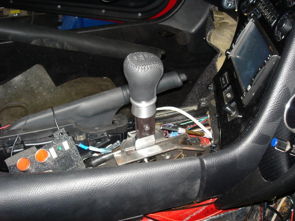
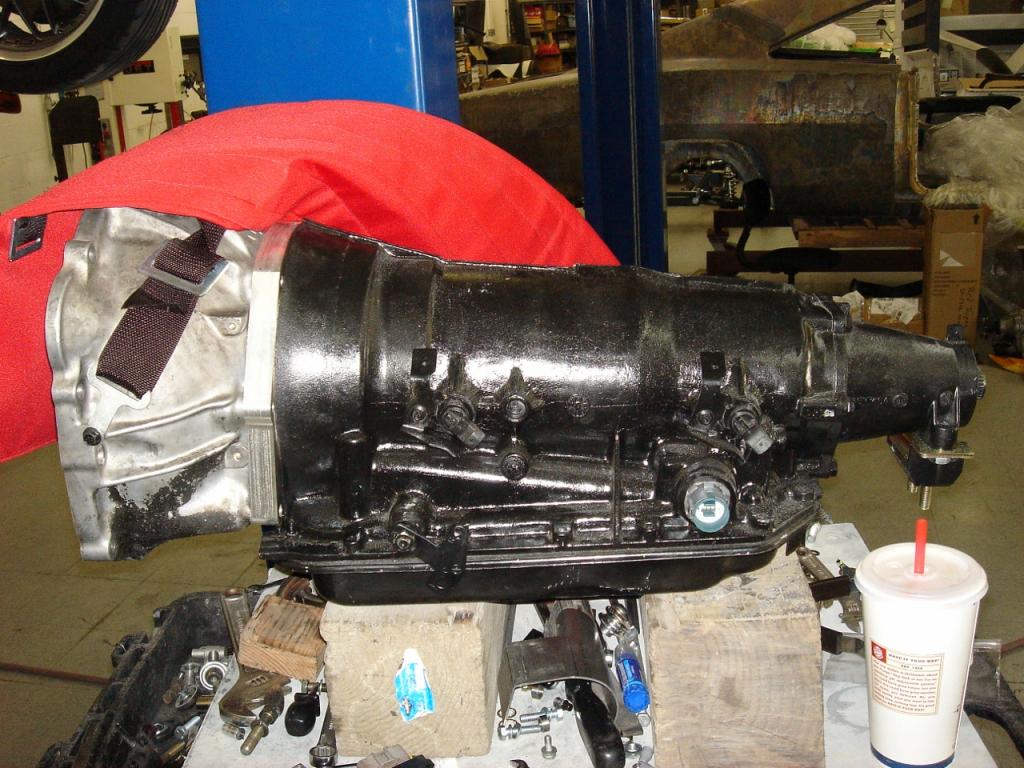
The GM 4L80E transmission has a ratchet shifter that allows you to select between 4 forward gear positions (OD, D, 2, 1), thus it needs no separate button for overdrive on/off. In addition, there is no function with this setup to select between automatic and manual shift modes. The pictures below show the ratchet floor shifter and the 4L80E transmission. The ratchet shifter drives a cable into the transmission which controls a vacuum switched circuit. This vacuum switched circuit has three outputs that vary between +12V and GND, and the encoding of these three outputs indicates the range selected by the ratchet shifter. These three signal outputs in turn connect back to the ECU so it can determine the range selected.
Therefore, the challenge for this project was initially to design a simple circuit that could take the three 4L80E encoded outputs and decode them fully into P, N, R, D, 2, 1 outputs that interface with the ECU and drive the light bulb indicators on the instrument panel. It also had to drive an Overdrive Off light bulb indicator in the dash and into the ECU (this is the way you map the 4L80E floor shifter to look fully like the stock A340E floor shifter, the overdrive signal distinguishes between OD and D). In addition, this circuit would also take as input the manual mode button that will be used for another feature explained below.
But, I wanted to do much more than that. I wanted to drive a 4D Systems 160x128 pixel OLED display that would show the selected range, the actual forward gear position being driven by the ECU when in the OD, D, 2, 1 ranges, the lockup status of the torque converter (the torque converter has a single disk clutch that can be locked up while in a steady state cruise to conserve gas), whether the car was in automatic/manual shift mode, and to show a clock (I removed the stock clock so I could install another gauge in its position). Two signals from the ECU drive gear shift solenoids on the transmission and these can be used to decode the forward gear position. One signal from the ECU drives the lockup solenoid on the torque converter and this can be used to decode the lockup state. I had one other idea which was to support paddle shifters off the steering wheel. These would have to be custom made later. I didn’t want to have to run wiring between the paddle shifters and the circuit I was going to design, so I wanted a fully wireless solution. In addition, these paddle shifters can only be enabled when the driver has selected manual shift mode.
With the exception of driving the OLED display and interfacing the paddle shifters, I could have designed a simple state machine and blown it into a programmable logic device. But because of those additions, I had to have a programmable solution via an embedded controller. I looked for a while into using a PIC controller, but then I came across the Propeller and was intrigued by its 8 core solution which I knew would be easier to program for multiple parallel functions than an interrupt based approach. Thus, I settled on the Propeller.


I have had this car for about 10 years now and during that time managed to break the stock automatic transmission (Toyota A340E) three times due to the power level I am at (~900 crank HP). Several years ago I decided to fix that problem once and for all by changing the transmission over to a GM 4L80E, which is a heavy duty transmission that GM used in its trucks. Both the A340E and 4L80E transmissions are 4 speeds with an overdrive gear. We got the GM 4L80E to work pretty well but I wanted to go a step further and make the transmission install look like it was completely stock. This means mainly 2 things. First, that the dash light indicators for the automatic range would reflect exactly the range position selected by the ratchet shifter for the 4L80E transmission. Second, I have an aftermarket ECU in the car and I wanted to make the transmission and its operation look to the ECU like it was controlling the stock A340E transmission. There are some subtle differences that require an electronic solution to fully address.
The stock A340E transmission has a floor shifter that allows you to select between 3 forward gear positions (D, 2, 1) and it has a button on the shifter to turn overdrive on/off and another button to select between fully automatic shift mode (ECU fully drives shifting and forward gear selection) and a sport manual shift mode (user shifts and makes all forward gear selections). The pictures below shows the stock floor shifter and the A340E transmission.


The actual range position selected by the stock floor shifter drives a mechanical gear selector indicator on the transmission. This mechanical gear selector is like a multi-way switch that separately indicates +12V or OFF for the R, P, N, D, 2, 1 positions. So, if the floor shifter is in the D position, then the D output from the mechanical gear selector will be switched to +12V. All other outputs will be OFF. These R, P, N, D, 2, 1 outputs from the mechanical gear selector feed into the ECU so it can determine what range has been selected. For example, if the range is D and the overdrive button is switched on, the ECU can drive the gear shift solenoids between gears 1 through 4. If the overdrive button is switched off, the ECU can only drive the gear shift solenoids between gears 1 through 3. In addition, the P and N outputs feed into a neutral start switch that controls the starter so that the car can only be started in those two positions. Finally, the mechanical gear selector outputs separately control P, N, R, D, 2, 1 light bulbs on the dash instrument panel, so the user can get a visual indication of the range selected that is right in front of them while driving.
The GM 4L80E transmission has a ratchet shifter that allows you to select between 4 forward gear positions (OD, D, 2, 1), thus it needs no separate button for overdrive on/off. In addition, there is no function with this setup to select between automatic and manual shift modes. The pictures below show the ratchet floor shifter and the 4L80E transmission. The ratchet shifter drives a cable into the transmission which controls a vacuum switched circuit. This vacuum switched circuit has three outputs that vary between +12V and GND, and the encoding of these three outputs indicates the range selected by the ratchet shifter. These three signal outputs in turn connect back to the ECU so it can determine the range selected.


Therefore, the challenge for this project was initially to design a simple circuit that could take the three 4L80E encoded outputs and decode them fully into P, N, R, D, 2, 1 outputs that interface with the ECU and drive the light bulb indicators on the instrument panel. It also had to drive an Overdrive Off light bulb indicator in the dash and into the ECU (this is the way you map the 4L80E floor shifter to look fully like the stock A340E floor shifter, the overdrive signal distinguishes between OD and D). In addition, this circuit would also take as input the manual mode button that will be used for another feature explained below.
But, I wanted to do much more than that. I wanted to drive a 4D Systems 160x128 pixel OLED display that would show the selected range, the actual forward gear position being driven by the ECU when in the OD, D, 2, 1 ranges, the lockup status of the torque converter (the torque converter has a single disk clutch that can be locked up while in a steady state cruise to conserve gas), whether the car was in automatic/manual shift mode, and to show a clock (I removed the stock clock so I could install another gauge in its position). Two signals from the ECU drive gear shift solenoids on the transmission and these can be used to decode the forward gear position. One signal from the ECU drives the lockup solenoid on the torque converter and this can be used to decode the lockup state. I had one other idea which was to support paddle shifters off the steering wheel. These would have to be custom made later. I didn’t want to have to run wiring between the paddle shifters and the circuit I was going to design, so I wanted a fully wireless solution. In addition, these paddle shifters can only be enabled when the driver has selected manual shift mode.
With the exception of driving the OLED display and interfacing the paddle shifters, I could have designed a simple state machine and blown it into a programmable logic device. But because of those additions, I had to have a programmable solution via an embedded controller. I looked for a while into using a PIC controller, but then I came across the Propeller and was intrigued by its 8 core solution which I knew would be easier to program for multiple parallel functions than an interrupt based approach. Thus, I settled on the Propeller.


Comments
To install all this stuff into the car was going to be a pretty big job. I had other issues with all the aftermarket stuff that had been wired into the car before, so I decided to take care of cleaning up all the previous wiring and installing the new stuff I had designed. This was to take over 6 months to fully execute. The previous wiring was a nightmare, so we had to pull out the interior to clean up everything from front to back. We also fully built all the new wiring harness outside the car. When we turned the car on for the first time, the board basically worked in all respects, except one. The R light bulb indicator wouldnt come on when the floor shifter was in the R position, although the transmission really did go in reverse. I had used solid state relays to drive these light bulb indictors and the signals into the ECU, and it turned out the relays could not sink enough current for this R position. The reason is that when the car is in reverse, bigger lights in the rear are turned on too! So, we added an external relay to handle the extra current and then everything worked fine. Pictures below show some of the wiring carnage inside the car, the new wiring harness for this project outside the car, the controller board box placed in the passenger foot well, and the OLED display mounted in a gauge pod off the dash. You can actually see two of the plastic cases. It turns out that I designed yet another board full of micro relays to handle various switches in the cockpit that turn on nitrous, the shift light, etc.
The final thing we did on this project was design the paddle shifters. While there are paddle shifter kits on the market, none would properly fit on my stock steering wheel, so we had to go custom. Below are pictures of the CAD design and the 3D plastic printed prototypes. Were still waiting to get these CNC machined out of metal, which will probably happen in spring 2012.
The total SPIN code I wrote for this project is right around 5000 lines excluding any code I obtained from the SPIN library for the Dallas real time clock, the OLED serial driver, and a C like library. It does not yet include the code for the paddle shifters but that should be a pretty small addition. I also ended up writing a pretty nifty general purpose debouncer module for this project. It can debounce the input on every I/O pin on the Propeller using an integration approach that is more resistant to noise than other approaches. I may end up generalizing that a bit and submitting it to the Propeller Object Exchange in the future. I did submit the code for my OLED display which supported all the documented display functions as well as joystick input (I use this to scroll through various menus, change and select values, like the real time clock setting, a programmable shift light feature, etc).
A total of 5 cogs are used for this project:
I have seen quite a bit of automotive gear, and I have to say you did a nice job! I think your HW skills are pretty good if this is "rusty" for you!
Honestly, this is the first time I've seen a 3D printer used to make a sensible prototype of something! I have really been struggling with the idea of 3D printers because I had a machine shop and did quite a bit of CNC work, so I'm biased towards precision and quality.
Thanks! The reason we went with the 3D printer is so we could do multiple rounds of tweaks to just get it right at low cost before sending it off for the more expensive CNC machining. I'm told because of the twist in the design it will require a 5 axis machine.
I hope everybody who reads this thread takes notice of something Jim did that shows true engineering experience. Take a good close look at the second photo in post #2. I can't count the number of times I've seen forum posts that go something like, "I've got this board I designed, and now I've got to find an enclosure for it." Way to go, Jim! You picked the enclosure first and designed the board to fit it.
-Phil
Nah, 5 axis is for really crazy stuff. You could have this done in 2 operations with some soft jaws.
Good to know, now I'll go back to my shop and ask them for this simpler approach.
2.) How did you adapt the 4L80E to the engine-home made or custom made adapter plate?
-dan
1. AEM gen2 ECU. It controls both the engine and the transmission. You can get separate standalone transmission controllers for the 4L80E from a number of vendors (e.g. Powertrain Control Solutions, TCI, etc) but then you have to connect other signals like the throttle positions sensor, a tach line, etc that already go to the ECU.
2. If you look at the last photo in post #1, it shows the 4L80E transmission with a CNC machined adapter for the bellhousing from the stock A340E. The bellhousing on the 4L80E is huge! and would have required some major hammering on the transmission tunnel to get it to fit. Some have done it but it really butchers up the tunnel. With the stock A340E bellhousing there is only some slight massaging of the tunnel to get the rest of the 4L80E tranny to fit.
Well, your original rendering shows the paddles as 3 pieces, the handle, the arm, and the hinge. I would recommend keeping this approach, since if something breaks you can replace the broken part instead of remaking the whole piece. The arm is pretty easy looking, you have to look at the part from the second op first. What would be the most convenient way to hold the finished part, then figure out how to machine the first operation from the raw stock.
I look at the rendering and think the paddles would be very nice in a mahogany or walnut, then the arms in stainless, and the hinges in black oxided stainless or black anodized aluminum.
Another way to consider making it is to machine it straight, then put the twist in it by hand, this would be fairly common for 1 off parts of this type, or even production parts. You just grab one end in a vise, and use a crescent wrench to give it a twist, or some similar approach.
Also, the paddles could be easily cut out of solid carbon fiber plate and attached with screws.
One neat feature you could add is have the transmission go to manual mode when you depress both flap paddles, that way you could go to that mode without looking down to press your button. To go back to auto, pressing the button would be best and safest.
Yeh, I could except the manual mode input into the ECU is directly controlled by the button. If I had thought about it more during the design process, I would have made the tranny board control the manual mode input into the ECU and the manual mode button would have just been an input into the tranny board. As it is now, I will have the manual mode button set the ECU up for true manual mode shifting, then depressing both paddles will toggle from using the ratchet shifter to the paddles, and vice versa. Also, the paddles will only be usable when the ratchet shifter is in OD or D. If during paddle shifter mode, you move the ratchet shifter out of D to 2 it will return to ratchet shifter mode. Sounds a bit complicated but I can't think of any other way to logically make it work at the moment.
BTW I have a 1988 Supra Targa (not the turbo version of 1989). I have had it since new, but it is pretty much standard, and I have been really pleased with it.
With the stock ECU in the car there are protections that override the user in manual mode but I don't think it would take care of the condition of the user forgetting to downshift and therefore running at an RPM that would bog the car. With the aftermarket ECU in the car it's exactly like having a manual valve body. i.e. What the user does is exactly followed for shifting and you can do something very stupid like downshift at the wrong time. It's similar to having a real manual gearbox in that respect.
I made some vinyl labels that could be affixed over the face of a heater switch. Examples are shown by the picture below.
Here are the actual heater switches out of the dash and mounted in the dash. This setup, I think, gives the car a more stock look for all the add-on switches I need.
Wow and Wow!
Now to the important stuff: Do you run that baby in the quarter mile? ET?
Back in the day, I raced a Hemi Cuda with an engine built by the most famous hemi guys of all time: 900 HP to the ground. I bet your Toyota would smoke it!
--Bill
Bill,
The current turbo in the car is my 3rd one, having progressed from smaller turbos, and I have not ran the car with the latest turbo yet at the drag strip. But, with the previous turbo I was consistently doing 10.6's in the quarter mile. With the latest turbo I am putting out around 140 HP more to the ground, so I am expecting to get down to upper 9's to lower 10's. That's about as far as I want to go with the car, but it's not bad for something that weighs nearly 4000 lbs with me in the car. The only thing holding me up from drag racing again is we have not got the nitrous setup working again; it's all wired in but there is some issue/bug with the AEM aftermarket ECU we are still trying to sort out.
I had no idea the Toyota weighed that much. My '70 Barracuda "only" weighed 3600 pounds, off the assembly line. The best I ever turned was 10.26. You are going to bury that time. Take some weight off that sweetie, somewhere! Or, is your goal--as you implied above--to maintain the stock look?
Merry Christmas!
--Bill
Bill,
The stock curb weight for automatic turbo with sport roof is just right around 3500 lbs. Throw in the additional weight for a stereo system, the roll bar, much heavier turbo system and transmission over stock, and my own weight of 200 lbs and the result is somewhere between 3900 to 4000 lbs. I weighed the car with myself on a truck scale and it came out to just under 4000 lbs. Not sure how accurate those weight scales are so maybe it's +/- 100 lbs. My 60 foots on the smaller turbo were around 1.60. I feel with my new turbo and a revised staging setup for the nitrous that I'll shave that down to the 1.40's. That should cut the overall ET down to around 10.2 to 10.3. Throw in the extra 140 hp and it should be good to just clip into the 9's. Goal is to keep it mostly like a stock car with the appropriate safety equipment but I don't want to go so far as installing a full cage. If I get down to the 9's I'll probably be kicked off the track, but it'll be worth it to see what it can do once.
You have a Merry Christmas too!
JimE
Your Toyota is a real street sleeper! The hemi Cuda was not . . . tunnel ram manifold holding two Holley 850 gear-driven quad double-pumpers sticking through the hood. The big cube roller motor had to turn about 3500 rpm to move the Cuda. (I drove it on the street!) It was not a street sleeper, for sure. But, it was fun in a totally different way than your Toyota. It was a Purple 427 Vette Eater!
--Bill
ps I'm too old to be thinking like this. I shouldn't have these thoughts at my age.
We where only paying 50 cents a gallon back then, too.
You're never too old for these thoughts. My dad just turned 80 years old this year and he has a red supra with a single turbo in it too, but with the 6 speed manual which is a really sweet transmission made by Getrag. He actually got me interested in these 4th (and last) gen Supras at a time before anyone knew how easy and far they could be modified. My engine is not built and is still going strong after 120K miles on it. The problem these days is most of the young folks know that supras can be easily modified and you never know when you're running along side one with 600 rwhp or 1000 rwhp until they open it up. I miss the bottom end torque but with a brake stall of 3800 and an automatic shift down a gear it comes on pretty fast once you're out of 1st gear. The shifts on this transmission are around 100 mSecs so it's easy to get down a gear into the right RPM band (and a bit scary too).
Your Cuda sounds like it was a very nice car. I grew up during the muscle car era so I still have an affinity toward the whole genre.