Triangulation with a Ping))) Array
 Phil Pilgrim (PhiPi)
Posts: 23,514
I'll be up-front: this is a project that received more of my time and effort than the results may have justified. Maybe if I put it down in writing, I'll be able to get it out of my system for good. My objective was to see if an array of Ping))) ultrasonic rangers could be used to determine not just distance, but an (X,Y) position of any object that lay before it -- most importantly -- without any mechanical scanning. I was only moderately successful. Here's what I did.
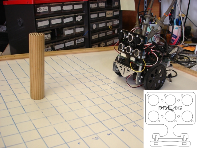
I first made a holder for three Ping)))s, oriented vertically, with a horizontal spacing of 1.05 inches. With this spacing, I was also able to accommodate a piggy-backed Propeller Backpack and a Proto-DB board, the latter outfitted with some three-pin headers and series resistors to interface the Ping))) to the Propeller chip. Here's a photo of the unit mounted to a BOE-Bot in my experimental setup, along with an inset showing the artwork for the holder:

The idea was to stimulate the three Ping)))s simultaneously, then analyze the timing of the three echoes to determine not only the distance of a subject before it, but its horizontal position as well. One of the first things I discovered is that, since the Ping)))'s SX chip is not crystal-controlled, the actual sonar burst can occur at varying times after the stimulus pulse. For this reason, among others, I decided to block the transmitting transducer in the two outside Ping)))s with foam, in order to read echoes from just the center transducer. You will notice the foam discs adhered with double-stick tape to the transducers in the photo above. The way it works is this:
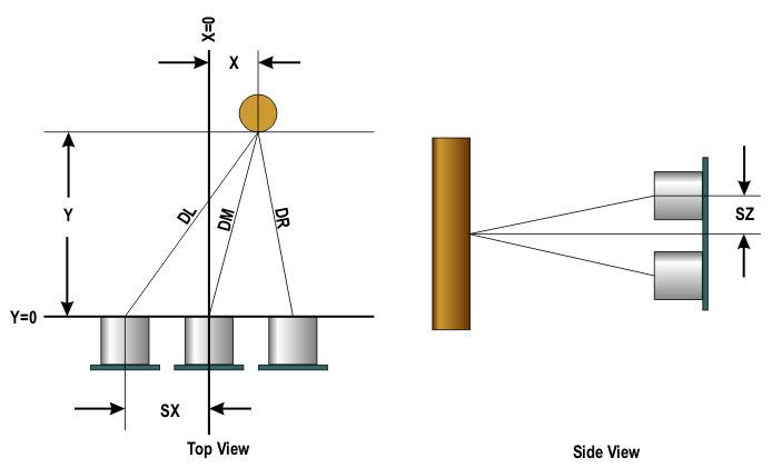
By analyzing the three times, it should be possible to determine, by triangulation, both the X and Y position of the subject. Here's a diagram that shows the basic geometry:

The equations that govern the X and Y coordinates are as follows:
where
and the T's are round-trip echo times, with a being a constant of proportionality relating time to distance. After these are computed, each can be corrected for the SZ offset:
By subtracting pairs of the corrected equations for the D's, the Y terms cancel, and we can solve each difference for X:
Obviously, with three Ping)))s, X is over-specified. So, hopefully, given a set of D's by experimentation, each equation will yield the same value for X. Unfortunately, that was not the case, a fact which had me stumped for quite awhile.
You may have noticed the scope leads attached to my setup in the above photo. Each monitored one of the Ping))) signal pins. What it told me was that each timing output included two forms of jitter: a microsecond or two of random noise, plus an increment or decrement of 25 µsec from the dominant falling edge. Twenty-five microseconds just happens to be one period of 40 KHz, the frequency of the ultrasonic transducers. This means that a round-trip distance measurement can bobble by one wavelength, or 0.34" (0.17" one-way). So instead of three over-specified arcs that intersect at a single point, we have three rather broad brush-stroked arcs, whose thickness spans a full ultrasonic wavelength (i.e. ± two half wavelengths) and whose intersection, hopefully, defines a rather small area. By locating the point in this intersecting polygon that satisfies all three equations for X, we can find the One True X.
In the attached Spin program, the search for X is done by brute force. IOW, X's are computed for each of several different combinations of values about the three D's, seeking to minimize their overall difference. The group of X's that is most tightly clustered wins, and their values are averaged. From that average, Y can then be computed:
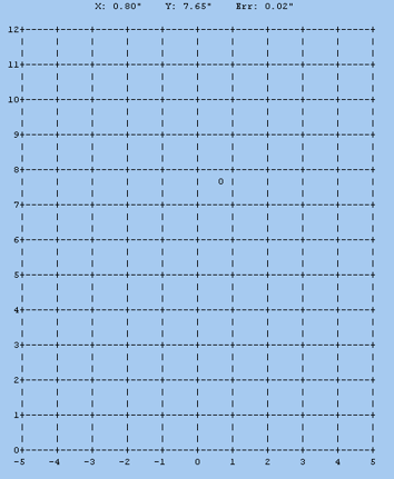
From there, a running average of the X, Y values can be maintained and plotted on a PST screen:

One Spin note: all three Ping)))s are timed simultaneously, beginning at the rising edge of the output from the middle one. This is done with counters for the left and right sensors, and by software alone for the center one, using cnt.
I got pretty good, but not perfect, results -- usually within an inch or less of the target's true physical position. As the angle of the target widened away from the normal acceptance cone of the farthest transducer, results got pretty sketchy. But I guess that's to be expected. Nonetheless, the accuracy is probably good enough for, say, following a leader robot at a fixed distance. In any event, I don't plan to pursue this any further. I've gotten what satisfaction I can from this project and need to move on to other things.
As always, questions and comments are invited.
-Phil
I first made a holder for three Ping)))s, oriented vertically, with a horizontal spacing of 1.05 inches. With this spacing, I was also able to accommodate a piggy-backed Propeller Backpack and a Proto-DB board, the latter outfitted with some three-pin headers and series resistors to interface the Ping))) to the Propeller chip. Here's a photo of the unit mounted to a BOE-Bot in my experimental setup, along with an inset showing the artwork for the holder:
The idea was to stimulate the three Ping)))s simultaneously, then analyze the timing of the three echoes to determine not only the distance of a subject before it, but its horizontal position as well. One of the first things I discovered is that, since the Ping)))'s SX chip is not crystal-controlled, the actual sonar burst can occur at varying times after the stimulus pulse. For this reason, among others, I decided to block the transmitting transducer in the two outside Ping)))s with foam, in order to read echoes from just the center transducer. You will notice the foam discs adhered with double-stick tape to the transducers in the photo above. The way it works is this:
1. Stimulate all three Ping)))s simultaneously.
2. The two outside Ping)))s don't actually transmit any ultrasound, due to the foam blocking their transducers.
3. Time the response of each Ping))), beginning with the rising edge output of the center one to the falling edge of each.
4. The timed responses give the round-trip distance from the center transmit transducer to each receive transducer.
By analyzing the three times, it should be possible to determine, by triangulation, both the X and Y position of the subject. Here's a diagram that shows the basic geometry:
The equations that govern the X and Y coordinates are as follows:
DL2 = (X + SX)2 + Y2
DM2 = X2 + Y2
DR2 = (X - SX)2 + Y2
DM2 = X2 + Y2
DR2 = (X - SX)2 + Y2
where
DM = aTM / 2
DL = aTL - DM
DR = aTR - DM
DL = aTL - DM
DR = aTR - DM
and the T's are round-trip echo times, with a being a constant of proportionality relating time to distance. After these are computed, each can be corrected for the SZ offset:
D := √(D2 - SZ2)
By subtracting pairs of the corrected equations for the D's, the Y terms cancel, and we can solve each difference for X:
XLM = (DL2 - DM2 - SX2) / (2 * SX)
XMR = (DM2 - DR2 + SX2 / (2 * SX)
XLR = DL2 - DR2) / (4 * SX)
XMR = (DM2 - DR2 + SX2 / (2 * SX)
XLR = DL2 - DR2) / (4 * SX)
Obviously, with three Ping)))s, X is over-specified. So, hopefully, given a set of D's by experimentation, each equation will yield the same value for X. Unfortunately, that was not the case, a fact which had me stumped for quite awhile.
You may have noticed the scope leads attached to my setup in the above photo. Each monitored one of the Ping))) signal pins. What it told me was that each timing output included two forms of jitter: a microsecond or two of random noise, plus an increment or decrement of 25 µsec from the dominant falling edge. Twenty-five microseconds just happens to be one period of 40 KHz, the frequency of the ultrasonic transducers. This means that a round-trip distance measurement can bobble by one wavelength, or 0.34" (0.17" one-way). So instead of three over-specified arcs that intersect at a single point, we have three rather broad brush-stroked arcs, whose thickness spans a full ultrasonic wavelength (i.e. ± two half wavelengths) and whose intersection, hopefully, defines a rather small area. By locating the point in this intersecting polygon that satisfies all three equations for X, we can find the One True X.
In the attached Spin program, the search for X is done by brute force. IOW, X's are computed for each of several different combinations of values about the three D's, seeking to minimize their overall difference. The group of X's that is most tightly clustered wins, and their values are averaged. From that average, Y can then be computed:
Y = √(DM2 - X2)
From there, a running average of the X, Y values can be maintained and plotted on a PST screen:
One Spin note: all three Ping)))s are timed simultaneously, beginning at the rising edge of the output from the middle one. This is done with counters for the left and right sensors, and by software alone for the center one, using cnt.
I got pretty good, but not perfect, results -- usually within an inch or less of the target's true physical position. As the angle of the target widened away from the normal acceptance cone of the farthest transducer, results got pretty sketchy. But I guess that's to be expected. Nonetheless, the accuracy is probably good enough for, say, following a leader robot at a fixed distance. In any event, I don't plan to pursue this any further. I've gotten what satisfaction I can from this project and need to move on to other things.
As always, questions and comments are invited.
-Phil


Comments
I bought a few "alternate" ultrasonic sensors off ebay. The SRF-04 units can be had for just$5, but I certainly got what I paid for. They can't hold a candle to a Ping, the results are quite erratic compared to a very stable, reliable, and accurate Ping.
This is very interesting.
Have you considered using your own transducers and driving circuits so you can have more control over the input to the transducers and better monitor the returned signal(s)?
I've wondered what one could do with an array of transducers listening in on a ultrasonic ping. Is it possible to build some sort of image out of the all the information generated? I've wondered if there's some way of generating an image similar to what "synthetic aperture radar" produces.
I'm pretty sure generating an image from ultrasound data is beyond my programming and math abilities. Is it even possible? I've purchased a couple of bare transducers than I plan to experiment with sometime. I haven't looked for driving circuits yet. I'm very curious about how much useful information could be gathered from having greater control over the transducers.
Would the returning signal have enough information to tell if the object detected was a flat wall? Wouldn't the echo from a wall be very different than an echo from a dowel? Thinking about extracting this type of data from the signals starts to make my brain hurt.
I've thought about these type of experiments as a possible application for multiple Propellers working together. Again, I really don't know how practical any of this would be but I thought this thread was a good place to share my musings.
Duane
Duane, I've thought about -- and tried -- several of the things you mention. A year or so ago, I set up four transmitting transducers in a row (driven with a Propeller via complementary-output MOSFET drivers) and one receiving transducer. The idea was to create a steerable ping by the relative phasing and timing of the signals going to the four transducers. But I did not meet with much success. Four transducers really aren't enough, and the ones I had created too narrow a beam. I even tried choking their apertures down to widen the beams but, for reasons I can't explain, that didn't work. (I repeated that attempt in the experiment described here with a similar lack of success. BTW, something else I've tried with the Ping)))s is a Fresnel zone plate (i.e. an acoustic lens) for beam forming. Unfortunately, the Ping))) doesn't have a long enough dead time to allow an adequate spacing between the lens and the transducer.)
Another approach would be to use a single, continuous, spherical-wave emitter and an array of receivers in order to derive a "sonic hologram", from which an image of sorts could be computed. I don't know if this is how medical ultrasonic imaging is done. But if you look up the kinds of transducers used for those apps, you will see that they require a rather large array of tightly-spaced transducer elements that operate at megaHertz frequencies to get the required resolution.
My experiments with ultrasonics have mostly been failures. In practice, ultrasonnic waves do not behave as one's intuition -- or even wave theory -- might predict. Add to that the varying speed of sound, due to temperature and humidity, and the difficulties presented by the native beam shape of whatever transducer you're using, and you end up with a prescription for frustration. At least that's been my experience.
-Phil
Thanks for the information Phil. I have plenty of frustrating projects already. I think I'll wait a while longer before I try to tackle ultrasound.
Duane
I had thought about using sonic, rather than ultrasonic, frequencies. At least it would make it easier to get a wider coverage angle from emitters the same size as those in the Ping))). Of course, the resolution goes way down, and it would be annoying to listen to!
-Phil
This is pretty cool, the results seem very useful.
I started on a project, probably about 5 years ago, to do something similar using a single transducer as the transmitter with an array of three transducers as receivers. I didn't get past the point of observing the echo's on a 'scope. It was evident from the timing of the echo's that the system would be workable, but I never took it to the stage of finishing the software. I think your results show that such a system should be revisited, or at least a modification could be made to PING))) to allow the trigger for timing to occur with out causing an actual ping so that one or more PING))) devices could operate in an echo only mode.
Neat stuff.
C.W.