

LED color Organ
 bomber
Posts: 297
bomber
Posts: 297
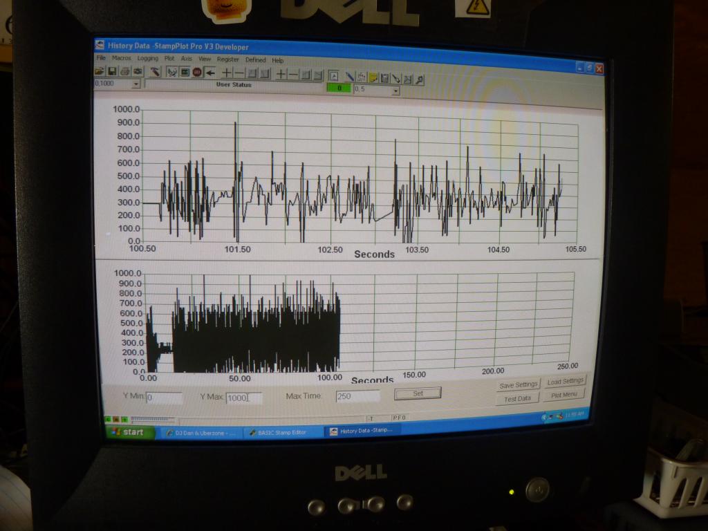
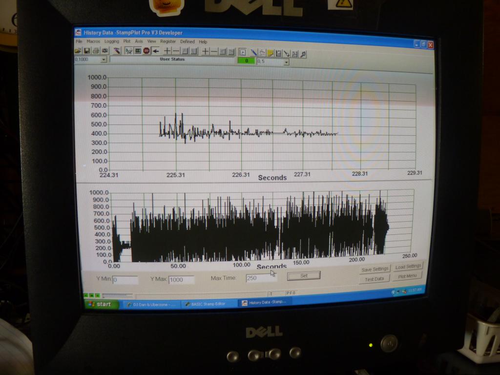
I built a LED color organ wit my BS2. It is hooked up to my computer speakers via a modified left speaker connected to an ADC. the BS2 samples the ADC and then decides which LED to light. And yes, those are straws on top of the LEDs. The straws act like light pipes, allowing the camera to see the light more clearly. I will post videos soon. I used Stamp Plot Proto graph the output from the ADC on my computer. In picture #3, you can see a black wire and a yellow wire coming off of the PDB. These two wires connect to my computer speakers. Enjoy!
Update: Added a 10K pot between aduio in and ADC in to stop the ADC from overloading if I am usng higher volumes. Also edited the code.
Finally finished the videos, and I am an hour early! Enjoy!
Please note: The aduio in the videos is low. I filmed these before installing the 10K pot and didn't have time to reshoot them.
Color organ with fireflies.

Color organ with freakazoid.
This video also shows the graph in action.
Sorry about the bad(ish) camerawork. Our tripod is a bit squeaky.
Update: Added a 10K pot between aduio in and ADC in to stop the ADC from overloading if I am usng higher volumes. Also edited the code.
Finally finished the videos, and I am an hour early! Enjoy!
Please note: The aduio in the videos is low. I filmed these before installing the 10K pot and didn't have time to reshoot them.
Color organ with fireflies.
Color organ with freakazoid.
This video also shows the graph in action.
Sorry about the bad(ish) camerawork. Our tripod is a bit squeaky.

1024 x 768 - 99K
1024 x 768 - 83K

1024 x 768 - 111K
1024 x 768 - 80K

1024 x 768 - 87K

1024 x 768 - 81K

Comments
I have a camera, although it takes a while to convert the video.
Uploading to youtube isn't an instant process, a 30 sec video can take... a few minutes.
Our camera, being a higher quality, outputs it's movies in a format called 'MTS' instead of 'Jpeg'. It requires special software to convert it to 'Jpeg'. Then, I can use Windows MovieMaker to edit the footage. Finally, I can upload it onto Youtube and the Forums.
Very interesting.
Stay busy.
When I was a small boy, there was a similar kind of version used in music stores by the store owners for marketing newly arrived cassette albums by playing them on tape decks and this light assembly being in circuit also. It's caught in my mind ever since :-) It's worth mentioning that in those days, there used to be 2 kinds of light organ assemblies; one regular version typically connected to the speaker's cable, the louder the volume, the stronger the flash, while another version connected directly to the "Pre", i.e the pre-amplification or before the circuit entered the amp, the signal coming from the playback-head.
I'm more interested in the later one :-) reason being very simple; for this one, one doesn't necessarily have to open a louder volume, even on headphones one can have the light show. There used to be a separate amp kind of thing for light organ, one circuit from the 'pre' entered this 'amp' for light organ, which had a separate 'volume' too in case the recording level was down or the audible sound coming from the amp connected in series was to be kept audibly low. This volume was raised to make light flashes more stronger.
Any suggestions for making such a circuitry in this regard would be highly appreciated as these assemblies especially for bigger lights aren't available in stores.
I would recommend trying the circuit and replacing the LEDs with Solid State Relays and connecting those to the lightbulbs. The video farther down the page is a good overall tutorial. You will have to build the circuit twice for stereo sound. I would NOT recommend recreating the circuit I have posted on the forum. I (foolishly) hooked an ADC parallel with the speaker and (somehow) got some functionality out of it. Happy Building,
Bomber
I purchased on of these chips a while ago. I keep hoping to add a visual display to my robot as it uses an Emic II.
I too was fascinated as a boy by the colors following the music. I built something using simple analog lowpass, bandpass, highpass, and each channel rectified fed a power driver, which was probably not much more than a transistor, although it might have been an SSR. I don't remember the details. The time-consuming part was fiddling with the two cutoff frequencies, which was difficult with the three separate filters. It would have been nicer to have two knobs for the two cut-points. I do recall it looked very nice with Japanese Koto music.