

Cheap PropPlug replacement - USB-TTL converter US$4.60 and a modification
 Cluso99
Posts: 18,071
Cluso99
Posts: 18,071
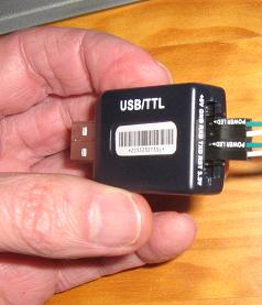
A few weeks ago I spied this USB-TTL converter on eBay. Some even came inside a plastic case. I bought mine direct from www.buyincoins.com for US4.58 including postage to Australia.
It uses a CP2102 USB to UART chip from Silicon Labs. Unfortunately, it uses a QFN package. On the output pin header it has (from left to right) +5V, GND, RXD, TXD, RST, 3V3. Now the RST is an input pin to reset the CP2102 externally.
The modification I did was quite simple...
1. I cut the RST input track before the pullup resistor
2. I scraped and tinned the RST track on the connector side
3. I soldered a wire from the CP2102 DTR pin 28 (top left pin) to the tinned track *****
***** BEWARE ! Soldering the wire to the QFN CP2102 is quite difficult, to say the least.

Now, next I made a big mistake...
I just connected the relevant 4 pins (GND, RST, TXD, RXD) to my TriBlade board and applied external power. I then plugged in the USB-TTL converter into my laptop. I had done this previously with TXD & RXD linked together and so I knew the driver was already working. I then loaded PropTool and searched for the prop.
Now for my error... NO NO NO. It DID find my prop! Yes, I had forgotten about the transistor reset circuit. I proceeded to download a simple program to flash a LED. It worked. I could reset my pcb and download again and again.
Now, I am unsure how long, without the transistor reset circuit, this is going to work, but certainly it IS working now.

It uses a CP2102 USB to UART chip from Silicon Labs. Unfortunately, it uses a QFN package. On the output pin header it has (from left to right) +5V, GND, RXD, TXD, RST, 3V3. Now the RST is an input pin to reset the CP2102 externally.
The modification I did was quite simple...
1. I cut the RST input track before the pullup resistor
2. I scraped and tinned the RST track on the connector side
3. I soldered a wire from the CP2102 DTR pin 28 (top left pin) to the tinned track *****
***** BEWARE ! Soldering the wire to the QFN CP2102 is quite difficult, to say the least.
Now, next I made a big mistake...
I just connected the relevant 4 pins (GND, RST, TXD, RXD) to my TriBlade board and applied external power. I then plugged in the USB-TTL converter into my laptop. I had done this previously with TXD & RXD linked together and so I knew the driver was already working. I then loaded PropTool and searched for the prop.
Now for my error... NO NO NO. It DID find my prop! Yes, I had forgotten about the transistor reset circuit. I proceeded to download a simple program to flash a LED. It worked. I could reset my pcb and download again and again.
Now, I am unsure how long, without the transistor reset circuit, this is going to work, but certainly it IS working now.

629 x 328 - 40K
238 x 277 - 12K
Comments
A longer time ago I watched a schmartboard video. These Schmartboard-PCBs seem to be quite simple to solder with a small but common solder-iron, because of the special surface of their PCBs
keep the questions coming
best regards
Stefan
For propeller-heads in germany this is an alternative. It uses the same Chip CP2102 and you can solder Pins to the small PCB.
I haven't checked the order of the Pins. Maybe a Pin-order-changing adapter is nescessary to be propplug-compatible
http://www.elv.de/output/controller.aspx?cid=74&detail=10&detail2=28776&flv=1&bereich=&marke=
If you order the device no pins are soldered.
I have tested it on a breadboard without reset-transistor just a capacitor like mentioned in the propeller-datasheet.
I even left out any kind of capacitors between Vss and Vdd and it worked reliable up to 115200 baud. Even with Viewport which sends data all the time.
best regards
Stefan
Digikey lists just the part for $3.17,
This list the module with USB connector and pins for $3.96
http://cgi.ebay.com/USB-2-0-TTL-UART-6PIN-CP2102-Module-Serial-Converter-/250847923910?_trksid=p3284.m263&_trkparms=algo%3DSIC%26its%3DI%26itu%3DUCI%252BIA%252BUA%252BFICS%252BUFI%26otn%3D21%26pmod%3D160615512814%26ps%3D54
It's the same chip CP2102. But a different connector and a different PCB as the chip is mounted diagonal.
But I guess same functionality with all UART-signals connected to the 0,1" through-holes
Does this one include Rx/Tx activity LEDs like the Prop-Plug?
best regards
Stefan
Looks like J1 pin 1 is the DTR pin. While it does not have the box like my find, it is easier to solder a pin header into J1. The cables are also provided too! Just a matter of hooking them up in the correct order (GND, DTR, TXD, RXD ---> Gnd, -RST, P31, P30). 5V is also available. 3V3 is also available up to 100mA MAX!
How to make a propplug compatable cable with the provided cables:
1. Fit each connector onto a 4 pin header (or longer - just use first 4 pins)
2. As you do this, place a small dab of super glue onto the side of the connector so that when you put it onto the pin header, it becomes glued to the adjacent header.
3. Do this for all 4 headers (3 glued joints)
4. Wait till they dry
5. Remove and label orientation - tip: use whiteout
6. Now, connect the other ends to the relevant pins
7. Cover the pcb with heatshrink tubing
he found the one at ebay that has moderate shipping fees
best regards
Stefan
If D1 doesn't provide bidirectional indication (it probably doesn't), adding an LED should be simple.
Thanks to Ray and all for pursuing this!
I connected LEDs to the Tx and Rx-line buffered through a OP-Amp-voltage-follower to draw as less current away from the Tx/Rx-lines as possoble.
If I sended/received data the LEDs flashed only very short at higher baudrates almost not visible. With the FDTI-chip the extra LED-outputs give always
a bright shining LED regardless of the baudrate. To reach this brightness I guess a monoflop would be needed that creates a high-signal that is long enough
to make the LED light up bright. And then there is almost no difference in price but more work to do than with a prop-plug.
@Cluso: please report how LEDs connected to your converter are lighting up
best regards
Stefan
I wonder if the persistence of the human eye would provide the necessary pulse lengthening? A transistor might be used to dump the charge of a cap across the LED, creating a brief but intense light burst. The cap could be charged through a high value resistor.
The point to using these is to make a cheap and simple propplug replacement with as little modification as possible. Otherwise, it is simply not worth the exercise.
In addition - once it works, if additional modifications are possible, then these are valuable as "advanced projects". For my purposes, they will be in a kid's education kit. The initial criterion is lowest price possible to get a usable unit. After a while, the kid may decide LED's for Tx and Rx would be nice. If a part can then be modded to add these, this part now has a greater value since it provides another project.
keep the questions coming
best regards
Stefan
No worries! Any addition I would be making would be added to the TTL side, and 0.1" pins make easy soldering targets. Indicator lights are just a nicety anyway.
Thanks for the heads-up on the role of D1. I think I'll try the flashing-LEDs/persistence-of-vision idea just for the educational benefit and to use up a few more five-cent transistors.
This is a really good idea. This would be a great example project.
I cut both the RX and TX line and inserted 10k resistors to keep the current to a minimum if either the propeller board or the USB connector is not powered. For a baud rate of 115200 10k might be already a bit too much if there's more than a few pF of capacitive load on the cable.
The transistor that pulls the reset line low sits together with the 100n capacitor on a piece of perfboard on top of the CP2102. The resistor at the base of the transistor is integrated in the transistor package (PDTC143XT).
The RST pin is connected to the collector of the transistor after the trace it was previously connected to was cut.
The pin nomenclature on the CP2102 board cost me a few minutes as the input (as seen by the CP2102) is labeled TXD and the output is labeled RXD - i just thought it would be the other way round.
While I haven't done any kind of heavy testing, I have used it to program the propeller a few times with the project I'm currently working on. So far everything worked as expected.
For price of approx. USD 3.5 per board (shipping included) this is quite a good price/performance ratio.
http://www.ebay.co.uk/itm/ws/eBayISAPI.dll?ViewItem&item=150689787403&ssPageName=ADME:L:OC:GB:1123
At only $2.91 each including postage they seemed a good buy. I might modify one of them with a transistor so that it looks like a Prop Plug (I have a real one), but I mainly want them for use with other MCUs. I have a USB to RS-232 adapter, but it needs an RS-232 driver on the target MCU board.
FWIW, all my new pcbs have an onboard 3V3 regulator for 5V input and the transistor reset circuit (which can be bypassed with a solderable link). For the small added cost, it makes cheap USB-TTL usable, although I am attempting to bypass the USB chip entirely ATM.
here you go
It's working without a problem since then. Instead of the PDTC143XT you can use any kind of NPN transistor, if you connect a 10k resistor between base and emitter.
If you don't want to modify (cut tracks, directly solder to) the USB board, build the middle of the picture on a piece of perfboard or on a breadboard. Connect the TXD, RXD, GND to the existing pins on the edge of your board opposite the the USB connector; solder a pin to either RTS# or DTR# and also connect it to your circuit. Next connect Reset#, TXD, RXD and GND to your propeller board.
If you want to modify the USB board (see following pictures): On the bottom side cut the traces to TXD and RXD and insert your R2, R3 resistors there. (The two small black rectangles on the second and third pin from top). Also cut the trace leading to pin labeled RST (bottom of the picture). Connect one wire to the RST pin, connect another one to GND.
Build the circuit C1, R1, Q1 and attach it to your board. Attach the other end of the RST wire to the collector of Q1 and the other end of the GND wire to the emitter of Q1. Solder one additional wire from the side C1 that isn't connected to anything yet to either RTS# or DTR#. The rest of the solder joints seen are just for mechanically stability.