Hilbert Transform: Prop DSP
 Phil Pilgrim (PhiPi)
Posts: 23,514
One of the more important filters that can be applied to a communication signal is the Hilbert transform. What this transform does is to delay all the spectral components of its input by 90°. This is way different than just delaying the signal as a whole. It means that a 10KHz component gets delayed by 25µs, while a 4KHz component superimposed on the same signal gets delayed 62.5µs. The Hilbert transform is used in software-defined radios (SDRs), for example, for image cancellation and to demodulate continuous-wave (CW) and single-sideband (SSB) transmissions (reference).
Fortunately, it is possible to approximate the Hilbert transform with relatively simple finite impulse response (FIR) digital filters. Such Hilbert transform filters typically have a limited passband ranging from 10% to 90% of the Nyquist frequency. But within that range, they remain remarkably flat with a gain of one. This range is ideal for voice communications, which is intelligible between 300 Hz and 3000 Hz. A sampling rate of 6600 Hz would therefore yield a passband of 330 Hz to 2970 Hz.
My objective was to implement a Hilbert transformer with the Propeller that could run in real time for use in demodulating SSB transmissions. I was assisted greatly by this paper, "Efficient Implementation of 90 Degree Phase Shifter in FPGA". What makes the authors' approach so nice for Propeller implementation is that it involves no multiplies and a minimum of adds, subtracts, and shifts, due to their use of a ternary (-1, 0, +1) coefficient representation. A couple things about the paper were initially unclear, though. For one, they refer to their FIR filter structure as "Direct Form II", which is a term usually applied to IIR filters. What they really mean is that it's "Direct Form Transposed." The other thing that I didn't realize is that "time zero" for the filter coefficients is the central term, not the first term. I kept getting frequency-dependent phase shifts and couldn't figure out why. It wasn't until further research that I realized that the input has to be delayed by half the FIR coefficient array size to align properly with the output. Once I added the delay routine, things worked as they should.
Attached is the code archive that implements and demonstrates the Hilbert filter. One complete cycle through the filter takes 4.250 µs with an 80 MHz clock. I've written it in such a way that it can be pipelined with processing in other cogs, if necessary, which would provide even faster throughput. This is done by outputting the result from the final FIR stage before processing the ones that come before it. But, for audio, it's fast enough without pipelining, and there's enough cog RAM left over for significant additional processing routines.
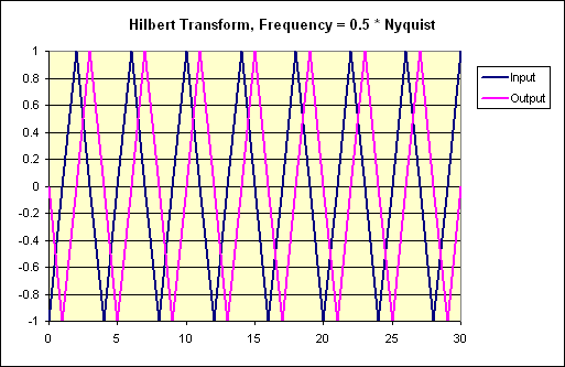
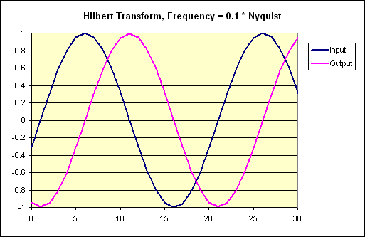
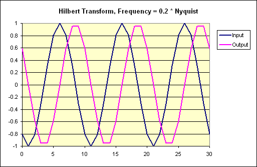
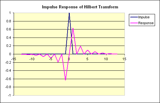
Below are some graphs I created from the demo program's output, plotted in Excel:


My long-range goal is to use this in conjunction with an I/Q demodulator like the one described here for better reception and filtering of SSB signals. It's entirely possible to demodulate SSB with the method presented in that link. But an interfering signal in the opposite sideband's frequency range (i.e. an image) would garble the result.
I also plan to explore further the methods used here for FIR filter construction for use in more generalized FIR filters on the Propeller.
-Phil
Fortunately, it is possible to approximate the Hilbert transform with relatively simple finite impulse response (FIR) digital filters. Such Hilbert transform filters typically have a limited passband ranging from 10% to 90% of the Nyquist frequency. But within that range, they remain remarkably flat with a gain of one. This range is ideal for voice communications, which is intelligible between 300 Hz and 3000 Hz. A sampling rate of 6600 Hz would therefore yield a passband of 330 Hz to 2970 Hz.
My objective was to implement a Hilbert transformer with the Propeller that could run in real time for use in demodulating SSB transmissions. I was assisted greatly by this paper, "Efficient Implementation of 90 Degree Phase Shifter in FPGA". What makes the authors' approach so nice for Propeller implementation is that it involves no multiplies and a minimum of adds, subtracts, and shifts, due to their use of a ternary (-1, 0, +1) coefficient representation. A couple things about the paper were initially unclear, though. For one, they refer to their FIR filter structure as "Direct Form II", which is a term usually applied to IIR filters. What they really mean is that it's "Direct Form Transposed." The other thing that I didn't realize is that "time zero" for the filter coefficients is the central term, not the first term. I kept getting frequency-dependent phase shifts and couldn't figure out why. It wasn't until further research that I realized that the input has to be delayed by half the FIR coefficient array size to align properly with the output. Once I added the delay routine, things worked as they should.
Attached is the code archive that implements and demonstrates the Hilbert filter. One complete cycle through the filter takes 4.250 µs with an 80 MHz clock. I've written it in such a way that it can be pipelined with processing in other cogs, if necessary, which would provide even faster throughput. This is done by outputting the result from the final FIR stage before processing the ones that come before it. But, for audio, it's fast enough without pipelining, and there's enough cog RAM left over for significant additional processing routines.
Below are some graphs I created from the demo program's output, plotted in Excel:


My long-range goal is to use this in conjunction with an I/Q demodulator like the one described here for better reception and filtering of SSB signals. It's entirely possible to demodulate SSB with the method presented in that link. But an interfering signal in the opposite sideband's frequency range (i.e. an image) would garble the result.
I also plan to explore further the methods used here for FIR filter construction for use in more generalized FIR filters on the Propeller.
-Phil


Comments
Does this have any audio applications ?
Bean
I can think of one offhand. It could be used when converting ultrasonic input to the audible range using an I/Q mixer to eliminate the negative frequency images in the result. For example, if you wanted to convert the frequency range from 30 KHz to 40 KHz to, say 1 KHz to 11 KHz, you would use a mixer having a local oscillator frequency of 29 KHz. Without image rejection or prefiltering of the ultrasonic input, you would also get mixer products from inputs in the 18 to 28 KHz range. By proper incorporation of a Hilbert transform in the processing software, the undesired "image" frequencies could be suppressed.
More generally, FIR filters have wide application in audio, since they can be used to implement lowpass, highpass, bandpass and notch filters, among others.
-Phil
Unfortunately, demodulation can be harder to implement compared to modulation, due to higher dynamic range required by receivers.
'Sounds interesting and would make a nice demo for the Propeller! Can you flesh out the theory/procedure a little for the binaural conversion?
Thanks,
-Phil
Maybe it needs more taps. Either that, or the coefficients require better precision. BTW, how did you arrive at your graph?
-Phil
-Phil