

Refrigerator Magnet Encoder
 Phil Pilgrim (PhiPi)
Posts: 23,514
Phil Pilgrim (PhiPi)
Posts: 23,514
Yesterday I received a pair of refrigerator magnets in the mail from a non-profit that wanted me to contribute money. Each measures 3.5"W x 2.75"H and consists of some flexible brown magnetic material as a backing, topped by a vinyl label with the non-profit's message. Planning just to throw them out, I placed them back to back, expecting them to repel each other -- you know, same poles. That's not what happened, though, They stuck together, offset vertically by a fraction of an inch. I could slide one across the other, and they would lock together in increments of what turned out to be 0.163".
Aha! Multipolar magnetic sheet! This could be useful!
I have some SS41 bipolar latching Hall effect sensors left over from an old project. When these are subject to a magnetic "north", they latch in one state; when subjected to a "south", they latch in another state. They seemed a perfect match for the refrigerator magnet material, so I set about to make a simple shaft encoder.
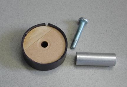
To do so, I peeled the vinyl label from one of the magnets and cut a vertical strip from it about 0.25" wide and 2.6" (16 x 0.163") long. This, I calculated, would wrap perfectly around a 0.83" diameter form that I could spin in front of the sensor to test it. I cut a disk with a hole in it from wood (D'ya see that Erco? WOOD!) using my laser cutter and adhered the magnetic strip with some double stick tape. Of course, I neglected to account for the thickness of the strip in my calculation and came up a little short, as the photo below shows:

I then mounted the disk on the standoff shown in the photo, chucked it up in my drill press, and placed the energized sensor next to it:

Here's an image of the scope trace it produced:

The gap is clearly visible, occurring every 16 pulses. To fix this I would have to make the disk a bit smaller. It would also be a good idea to wrap some thin tape over the strip to keep the ends from pulling away from the disk.
Anyway, this looks like an easy way to make an almost-free encoder from simple materials. For quadrature output, it's necessary only to add another sensor, offset n + 1/4 magnetic pole pairs from the first.
-Phil
Aha! Multipolar magnetic sheet! This could be useful!
I have some SS41 bipolar latching Hall effect sensors left over from an old project. When these are subject to a magnetic "north", they latch in one state; when subjected to a "south", they latch in another state. They seemed a perfect match for the refrigerator magnet material, so I set about to make a simple shaft encoder.
To do so, I peeled the vinyl label from one of the magnets and cut a vertical strip from it about 0.25" wide and 2.6" (16 x 0.163") long. This, I calculated, would wrap perfectly around a 0.83" diameter form that I could spin in front of the sensor to test it. I cut a disk with a hole in it from wood (D'ya see that Erco? WOOD!) using my laser cutter and adhered the magnetic strip with some double stick tape. Of course, I neglected to account for the thickness of the strip in my calculation and came up a little short, as the photo below shows:
I then mounted the disk on the standoff shown in the photo, chucked it up in my drill press, and placed the energized sensor next to it:
Here's an image of the scope trace it produced:
The gap is clearly visible, occurring every 16 pulses. To fix this I would have to make the disk a bit smaller. It would also be a good idea to wrap some thin tape over the strip to keep the ends from pulling away from the disk.
Anyway, this looks like an easy way to make an almost-free encoder from simple materials. For quadrature output, it's necessary only to add another sensor, offset n + 1/4 magnetic pole pairs from the first.
-Phil
431 x 296 - 24K

640 x 480 - 12K

593 x 498 - 55K
Comments
And wasn't that wood a friggin' JOY to work with?
How about an ultralight robot using 2 or 4 magnetic wheels like this that could climb a vertical steel surface? Do some precision odometry with the encoders and run some dead reckon on the fridge or file cabinet?
But I have a question: what happens if you can't get the poles to match just right when the strip meets up on itself after you wrap it around an object like that? Does that mismatch of poles mess up the encoder or is there a simple way to overcome the skipping of a pole?
Without a laser cutter, you can still produce a usable disk. Just chuck up one that's slightly oversize, as I've shown, but without the magnet. Then, with a file or sanding block, and with the disk spinning, work it down to the correct size. If you have a drill press vise, clamp a file in it and use that. It will keep the sides vertical. (My drill press is my lathe.
As an alternative, you can make the disk slightly undersized and build it up with tape before adhering the magnetic material.
-Phil
Using "magnaview" film would help out here to "see" the magnetic field, as shown in this nifty video: http://www.youtube.com/watch?v=TjxqW6GWpMs You can get a small piece of that film for a couple bucks: http://www.magnetsandhealth.com/catalog/product_info.php?cPath=55&products_id=617 or http://www.scientificsonline.com/magnetic-viewing-paper.html
Magnets are just plain cool, and I think this is a great application and wonderful find from Professor PhiPi!
The way I determined the pole width was to place one magnet back-to-back with the other, and let them lock in place. Then I measured the offset between their two edges with linear calipers. Next, I shifted one of the magnets by one pole position relative to the other, let it lock in place again, and took another measurement. The difference between the two measurements was the pole-pair width. I then used 16 * width / pi to get the disk diameter. But I should have subtracted twice the material thickness from the result, since the poles have to mate on the outside of the magnet surface, not the inside.
With the magnaview material, you wouldn't even need a scope to check for a gap. Just wrap the magnaview around the encoder disk and look for uneven spacing where the ends meet.
-Phil
Don't knock the gap, as it could be used as a reference sync.... although depending on the circumference, and how you cut the magnetic 'zebra strip' you either get a long extended pulse, or a small brief pulse. Either way a usable sync reference detection. ( Edit: well there is that rare chance that you could be spot on, in which case there wouldn't be any perceivable gap.)
As far as dead reckoning, the gap is still beneficial. Although it might introduce a small amount of error, the error is self correcting within each revolution and doesn't compound over distance.
You're right, of course. A friend of mine works with one of the car companies on their electronic ignition systems. Some cars, apparently, use an inductive pickup from a timing gear as an encoder and simply omit a tooth for the reference "pulse". This works great while the engine is running, but it does present some challenges for the ignition timing while starting the engine.
-Phil
Okay, just thought I'd drop that buzzphrase "linear encoder" here so I can find this later on using a search engine for this site. :-)
-Phil
If you want to bad enough, you can find the stuff in sheets and cut it so that it is striped perpendicular.
agfa
thanks
I stopped by Michaels today to see what I could find. Some of their magnetic sheets did not seem to exhibit the multipolar property. I did find some "business card magnets" that are multipolar with a spacing of about .125" I don't have the precision measurement capibility that Phil has. But I got some and connected my scope to a Melexis hall effect sensor (read Parallax) and was very much able to generate the nice square waves. The sheeting is 3.5" long so I need to come up with a wheel about 1.1' in diameter. For $3 and change I have 10 magnets to experiment with.
RS_Jim
If anyone wants some strips, I can cut them pretty good on the laser and get you a very nice square strip for wrapping acount a disk. I can even cut the disk in any size with the laser too.
I'm working on a robotic camera arm for my motorcycl project and will be using this idea for the feed back on the main arm turret. Since I have a base of 5.75" in diamater, I will get a pretty decent reference feed back for location. I'll also use two limit switches and maybe a center position on startup to know where I'm at.