

Poor Man's Digital Oscilloscope (now with VGA option and screen capture to SD)
 Perry
Posts: 253
Perry
Posts: 253
I have been working on this for some time and need to share
This is a "Dual Channel Oscilloscope" with vector mode v key to switch mode)
it uses two sigma/deltas , a keyboard and tv on a protoboard
Adapted from "raman"'s dual channel ADC, the code posted below works. but there is a problem I can not seem to resolve.
main controls are:
space" ... start/stop capture
"v" ...... switch from normal to vector mode
"F7" ....... decrease sample time
"F6" ....... increase sample time
left ...... increase attenuation
right ..... decrease attenuation
up ........ move display up
down ... move display down
added shift and ctrl to individually manage Channel A or B for movement and attenuation
My problem is that in the main program at line 185 I have to restart the ADC cog, instead of just resetting the buffer address. (it works if I restart the capture cog, I have another project in mind that needs more speed)
in the main program (Dual_Channel_Oscilloscope.spin
in Dual_Scope_ADC.spin
I have added two photos
the first is in XY mode showing the classic chaotic Chua's Circuit
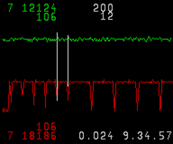
and the second in standard display showing the inputs from a video source
Have fun with it, and suggestions/improvements are desired
Just added VGA option
to build you need Dual_Channel_Oscilloscope.spin and Dual_Scope_ADC.spin
then chose one of TV_Graphics.spin or VGA_graphics.spin
code online now is TV version, to use VGA just change to the OBJ declaration and basepin
April 10 2011
added config file
changed to lonesock's Easy_ADC
updated code to allow writing to SD ram
April 13 2011
I wimped out and used FloatMath and FloatString to show timing info.
also added a simply function generator that you can toggle on/off with the "f" key
saved all files needed in the archive.
It's been reported that this version won't compile with Propeller Tool( run's out of memory)
You need " Brad's Spin Tool" http://www.fnarfbargle.com/bst.html which has a compiler option of "Eliminate unused SPIN methods"
April 16 2011
Another upload. I think there is not much more that can be done with this. There is not much memory left and only one cog
I might rethink the input mechanism.
added two function generators that each use a cog
function_1 square wave direct toggling of any pin max speed is maybe 500KHz
toggle on/off with "q" key
set its period with a number and then the "p"
function_2 sine wave ......... using the duty cycle (use your sound output pin) max almost 4000Hz
toggle on/off with "f" key
set its period with a number and then the "t"
presently you have to manually stop/start a function to see the change.
Apr 16 2011
Another update
changed function generators to accept input in Hz instead of period
change trace display to voltages instead of values.
This is a "Dual Channel Oscilloscope" with vector mode v key to switch mode)
it uses two sigma/deltas , a keyboard and tv on a protoboard
Adapted from "raman"'s dual channel ADC, the code posted below works. but there is a problem I can not seem to resolve.
main controls are:
space" ... start/stop capture
"v" ...... switch from normal to vector mode
"F7" ....... decrease sample time
"F6" ....... increase sample time
left ...... increase attenuation
right ..... decrease attenuation
up ........ move display up
down ... move display down
added shift and ctrl to individually manage Channel A or B for movement and attenuation
My problem is that in the main program at line 185 I have to restart the ADC cog, instead of just resetting the buffer address. (it works if I restart the capture cog, I have another project in mind that needs more speed)
in the main program (Dual_Channel_Oscilloscope.spin
    else
      adc.start(SampleTime, inpina, opina, nAverageA, nPeakA, inpinb, opinb, nAverageB, nPeakB)
'      adc.SetBuffer(@ScopeBuffer1)  ' This is how  it should work
in Dual_Scope_ADC.spin
PUB SetSampleBits(arg) ' use sampleTime not bits this one works
  long[@asm_cycles] := arg

PUB SetBuffer(argh)'  this one does not work
  long[@Buffer] := argh
I have added two photos
the first is in XY mode showing the classic chaotic Chua's Circuit
and the second in standard display showing the inputs from a video source
Have fun with it, and suggestions/improvements are desired
Just added VGA option
to build you need Dual_Channel_Oscilloscope.spin and Dual_Scope_ADC.spin
then chose one of TV_Graphics.spin or VGA_graphics.spin
code online now is TV version, to use VGA just change to the OBJ declaration and basepin
April 10 2011
added config file
changed to lonesock's Easy_ADC
updated code to allow writing to SD ram
April 13 2011
I wimped out and used FloatMath and FloatString to show timing info.
also added a simply function generator that you can toggle on/off with the "f" key
saved all files needed in the archive.
It's been reported that this version won't compile with Propeller Tool( run's out of memory)
You need " Brad's Spin Tool" http://www.fnarfbargle.com/bst.html which has a compiler option of "Eliminate unused SPIN methods"
April 16 2011
Another upload. I think there is not much more that can be done with this. There is not much memory left and only one cog
I might rethink the input mechanism.
added two function generators that each use a cog
function_1 square wave direct toggling of any pin max speed is maybe 500KHz
toggle on/off with "q" key
set its period with a number and then the "p"
function_2 sine wave ......... using the duty cycle (use your sound output pin) max almost 4000Hz
toggle on/off with "f" key
set its period with a number and then the "t"
presently you have to manually stop/start a function to see the change.
Apr 16 2011
Another update
changed function generators to accept input in Hz instead of period
change trace display to voltages instead of values.

640 x 480 - 36K

640 x 480 - 31K

720 x 480 - 64K
576 x 480 - 36K

576 x 480 - 38K

576 x 480 - 39K

192 x 160 - 1K


800 x 600 - 57K
Comments
right near the start of the main program
I assume you're using the standard 2-resistor ADC circuit where there's a 150k resistor from the signal source to the InPin and then a 100k resistor from the Opin to the InPin...
not quite, I use two 470K resistors but I suspect as long as the two resistors are pretty close it will work.
I am fine tuning the display and functions, but still can't figure why the setbuffer function does not work dynamically.
Well done Perry :-)
I saw some tiny 3.5" LCD NTSC displays on ebay the other day for
22.00 USD delivered. They might go well with this to make a small portable
package.
This goes way beyond audio, you can see the equalization pulses in the TV horizontal synchronization signal.
I have found one problem where I forgot to put # in front of a jump address
have uploaded replacements on first page
Are you using the QPF style of props or is the DIP40 good enough?
I have a couple of the quad sort but I always prototype with the DIP40s, There has always been comments on how the QUADs are really the only ones that hack the Sigma/Delta stuff, due to lead lenths etc.
I think that problems with sigma/delta have been much less than described. I can't see why they should not work on a DIP40, make sure you have all the bypass capacitors on every power supply.
My protoboard is quite "shop worn" in fact my "B" channel has had to get a little thread of wire to replace part of a PCB run that got burnt. Keep the leads to the feedback as short as you can, once you begin dealing with the input side of the input resistor you should have few concerns.
IF you can keep you board clean you should be able to sigma/delta circuits.
The sigma/delta ADC code will not actually work at 2.5MHz as documented, with the extra code I added it will do about 1MHz.
Because you use clock counts to get the ADC values the higfer the frequency attempted the lower the bit resolution obtained.
If you had a real ADC chip instead is sigmal/delta you would get better resolution and speed, should not be very hard to adapt this program for that.
Duane
-Phil
-Phil
Their basic limitation is in how fast one can write the ADC values into memory.
The other limitation is how fast the ADC can operate.
Sure, you can increase the speed by using 4 8-bit ADCs and storing the 4 samples in a 32-bit word.
But that is about as fast as you could go.
However, there is another configuration that can operate at much faster speeds.
These are the "Time Domain Sampling Oscilloscopes" or the "Frequency Domain Sampling Oscilloscopes".
The heart of these devices is a very fast sampler, or sample and hold.
There's always a trade off, in this case you take only 1 sample point each time the the waveform comes by.
So one must have a repeating waveforms.
The Time Domain type takes it's samples after delays from the trigger point.
The Frequency Domain type uses a phase locked oscillator synchronized to the trigger.
The Propeller is a natural with this second type because it has the Numerically Controlled Oscillators.
Once the sample is made an ADC can read it at a reasonably slow rate. Read this to mean
it can do it with high resolution.
Here is a "Idea For Design" from "Electronic Design" September 18th, 2000.
http://www.redrok.com/Circuits_1GHz-samplig-Oscilloscope-Front-End.pdf
Duane
It should be doable, it uses the Parallax standard TV driver.
Just before you start the TV driver try this:
Anyway, if you can't get that working, maybe another way is to use the USB serial connection to send the scope data from the Prop to the PC.
Just need to come up with some program or terminal window to display the data...
Hi Rayman. Thanks. I don't know about that but if my memory serves me right, I had distorting images when I connect the other way around. I'll definately be working on the at the sideline along with my urgent projects.
Cheers!
You got me thinkin' about your PrintScreenVGA, with slight modification and simple_serial you can do a hex dump of the screen with only 180 longs.
It should be easy modify this 'scope to run on VGA, I just don't have VGA connector on my proto board , so I can't test the changes !
:O that would be great!! I can test for you.
I just upgrade the front page of this thread for VGA, could some one try the VGA option.
Cool! I'll test this tomorrow morning when I'm back office. Don't have the board with VGA at home
Hello Perry,
I've tested but displayed nothing. The changes I've made were
and
Are there anything I need to change as well? On the hardware side, I'm using prop proto-board with mounted VGA/PS2 KB/Mouse connector and base 16 was tested OK.
Thanks a lot.