The "Lassiter" inexpensive (LIDAR) Distance Detection & Ranging - Propeller/WiiMote
The "Lassiter" Propeller based Lazer guidance/distancing Gadget Begins.
LIDAR (Light Detection And Ranging) is an optical remote sensing idea that can measure the distance to, or other properties of a target by illuminating the target with light - in my case laser light.
..... By using a simple parallax propeller system and hacking the IR camera out of the Wiimote and controlling it directly via I2C - its possible to measure distance very accurately on almost any surface.
The system seems to work better than InfraRed/Ultrasonic sensors.
Update 20110301 :- Chassis at the Ready
Having built the Lassiter i wanted to make it mobile so that it could go for a spin..........(with a spin)

Sooo....... Wots He Got

and compass to tag directional information

1st Video shows system working and detecting all kinds of surfaces and sized objects and walls.

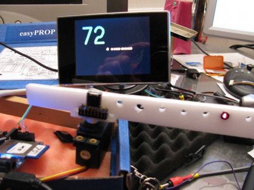
The above screen show the result of a simple scan, the screen acts as visual stora memory (the buffer for the screen holds the actual scan data), which will be used later for navigation.(ie find doorway to drive through).

2nd Video show the Sensitivity and Range possibilities.

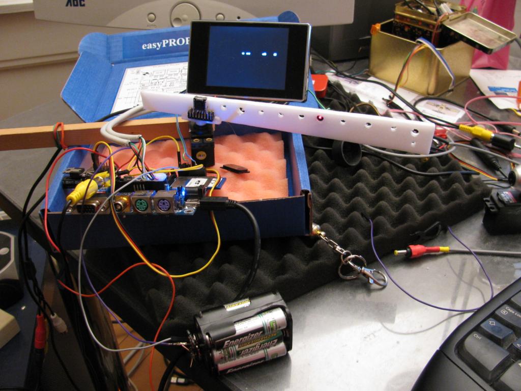
What you see here is my first successful setup :-


When and object is placed in front of the laser the reflected laser light hits the Wiimote, the closer the object the more to the right the dot on the display goes.
Why does this happen :- in a nut shell the laser and Wii-camera are set at an angle to converge with each other.

I was bogged down with converting a number to a string (as my memory was almost topped out with the wiimote/graphics/tv objs) so :-a drastically reduced "Numbers.obj" won the day for me and i could display variables to screen.
Even in this state its possible to measure distance (so far 2meters max)
The accuracy in this simple form is 0.5 mm ...... uncalibrated ......
The system will be used in my latest Robot as a navigation/distancing Probe.
3rd Video shows the basic system (before the numbers.obj)
4th Video shows the first "proof of concept" using InfraRed Leds
5th Video shows the Hacking process and removal of the IR camera from the Wii-Mote .
LIDAR (Light Detection And Ranging) is an optical remote sensing idea that can measure the distance to, or other properties of a target by illuminating the target with light - in my case laser light.
..... By using a simple parallax propeller system and hacking the IR camera out of the Wiimote and controlling it directly via I2C - its possible to measure distance very accurately on almost any surface.
The system seems to work better than InfraRed/Ultrasonic sensors.
Update 20110301 :- Chassis at the Ready
Having built the Lassiter i wanted to make it mobile so that it could go for a spin..........(with a spin)

Sooo....... Wots He Got
- Parallax Propeller chip 8 core multitasking risc processor
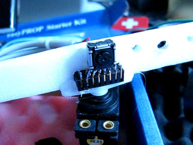
- Hacked WiiMote - camera removed and i2c interrogated to extract 4 blobs of light with XY coords
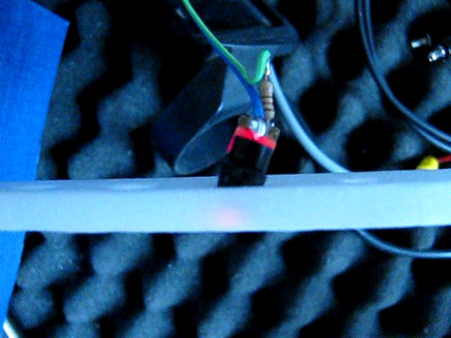
- Lassiter enabled LIDAR system - inc. 5mw Laser (please wear eye protection when using lasers)
- Colour Display screen - used for displaying data .....in graphical form
- Compass module .... so data can be logged with direction tags
- 2xPwm L293D motor drivers
- Omni wheels
- Optical Wheel Encoders

and compass to tag directional information

1st Video shows system working and detecting all kinds of surfaces and sized objects and walls.

The above screen show the result of a simple scan, the screen acts as visual stora memory (the buffer for the screen holds the actual scan data), which will be used later for navigation.(ie find doorway to drive through).

2nd Video show the Sensitivity and Range possibilities.

What you see here is my first successful setup :-
- Propeller easyProp board
- Hacked Wiimote camera mounted on servo
- 6 holes along the white Depron you can see a Laser
- Behind you see the lassiters composite video screen


When and object is placed in front of the laser the reflected laser light hits the Wiimote, the closer the object the more to the right the dot on the display goes.
Why does this happen :- in a nut shell the laser and Wii-camera are set at an angle to converge with each other.

I was bogged down with converting a number to a string (as my memory was almost topped out with the wiimote/graphics/tv objs) so :-a drastically reduced "Numbers.obj" won the day for me and i could display variables to screen.
Even in this state its possible to measure distance (so far 2meters max)
The accuracy in this simple form is 0.5 mm ...... uncalibrated ......
The system will be used in my latest Robot as a navigation/distancing Probe.
3rd Video shows the basic system (before the numbers.obj)
4th Video shows the first "proof of concept" using InfraRed Leds
5th Video shows the Hacking process and removal of the IR camera from the Wii-Mote .


Comments
So far it can be used to a distance of 3meters using a 5mw laser.
I'm trying to do a similar project, haven't started yet, and was wondering if you could you post the code that you used. Was there also a special reason on the angle/distance between the laser and the camera? Did you also test your setup outside? I'd assume it wouldn't work as well as theres allot of interference but maybe if you put a filter over the camera you could reduce the interference and thus get a better reading.
Code-ing is still pretty changeable so i will hold on posting till i am a bit further down the line, to give you an idea these are the OBJ files i use
they have to be drastically reduced especially the graphics.obj to save space for program.
tv : "tv"
gr : "Graphics"
wii : "wiicamera"
num : "Numbers"
HM55B : "HM55B Compass Module Asm"
Calibrate : "HM55B Compass Calibration"
The Wii-mote has an InfraRed filter as standard ...... this you have to remove for the Wii camera too see a stronger Lazer/laser reflected signal -- ambient light can be a problem - but as you see in the videos it is still pretty stable - A laser filter that should help.
this project is still pretty "hot off the press"
To help you with a few details .......
The wiicamera.obj gives a simple schematic of the camera connections
All you need to do then is add a forward pointing Laser at an angle to the Wiimote camera.
Hope this helps - i have no diagrams of the system yet as its still very new to me too.
The above set up is enough to get things rolling .
Currently i am trying to add 2 PWM motor controllers but program space to low.
.. I have worked with polar coords before with a gadget i made here "LoMoR" however memory was no issue then..(but processing power was)
Having built the Lassiter i wanted to make it mobile so that it could go for a spin..........(with a spin)
This is awesome!
I so want to get into this as soon as I'm done with the few other projects I've got going on...
I see you shared your wii object... most many THANK YOU's to you for that...
^5's and keep on it!
KK
Do you know if the CMUcam can detect the laser spot so that it could be used instead of the WiiCam?
I was thinking of getting the CMUcam3 for another project and am wondering if it would work here?
:-) ...... the object actually has been around for a while and was written by Graham Stabler 17th November 2009
Its been a fascinating project for me - i am awaiting a RBBB prop board to slimline things down a bit though.
My guess (and that is really a guess) is that it would work , try a normal video camera and check the brightness of a spot reflected off a wall, as far as i know the CMUcam3 checks for the brightest spots etc .. Dont forget that ambient light does have to to taken into consideration when using the reflected laser technique.
The accuracy is very good when the angle of the laser to the camera is wide (amazing at short distance) for long distance the angle needs to be narrow (then you lose accuracy).
I have mounted a laser to a servo with a fixed camera beside it - this way its possible to change the angle of the laser 2 camera.
This is a brilliant idea! Never thought long-range metering could be affordable in a home-made system.
Just an idea for improvement:
If you would place inexpensive linear lens (generates a static line from the point beam) and put the laser above the CAM, then you would see the whole 2D panorama in a single frame.
The "red" line above the center is closer to the camera, than dots below the center.
Will try to make photographs for illustration tomorrow if you are interested
Thanks for your Idea :-
Yes i think i follow what you mean (bit like the way of creating 3D images with a line laser), correct me if i am in the wrong ball-park.
Yes i am more than interested if you could post a picture to clarify .........that would be super.
I dont know if this is the laser mentioned above but
I found one of these diffractive optics filters attached to a multi-function laser tape measure. This small filter converts a single coherent beam from any common laser light into a diffracted beam with an angular field.
Ahaaa ...Now its clear...........For this type of Line laser, a normal camera would have to be used (any normal web cam objs out there ?)...
The Wii-camera can only decode the XY positions of points of light. (the wii camera would only pick out the 4 brightest points along the above mentioned laser line ...)
Hi!
Thank you tdeyle! I was talking abut the method in the link you posted!
And NikosG created the photos I was thinking of
It would be possible to build a cost-effecitve ranging system that could work parallel with Ping)))
Kind regards,
Attila
WOW... very interesting read...
KK
Sort of like how EYE's work? Maybe a second servo with some gear-down gears to mount the laser on? then the system could "adjust" it's focal point.
I kind of guess you are taking the distance from the camera and the angle of the laser to calculate the distance. Is that about right?
My attempts at buiding a laser range finder have been hampered by getting distance. I can get a laser to spot on something and have it picked up but accurate distance measuring has been my problem, particularly at higher speed.
Something that was brought up to me in a thread about using CD lasers. When working underwater two lasers are used. It helps with a number of problems, increase accuracy etc.
Heres my thread and others referenced various links.
http://forums.parallax.com/showthread.php?127505-Laser-Rang-Finder&highlight=laser
This is something I always planned to do, I was contemplating using multiple lasers, possibly strobe them for identification purposes.
I also had a go at the virtual white board thing, my tip is to use a surface mount IR led facing up at the camera, it is very accurate and they are no directional so are always picked up well.
Graham
I have to say this is one of the most useful objs around .....(totally bomb proof and so easy to use.....amazing) there are so many things you can do with the information and the whiteboard and lassiter are only just the start ..........over at letsmakerobots interest is picking up fast too.
My next plans are to use the whiteboard as a button/switch/slider designer for analoge/digital type inputs ....ie draw your buttons with an IR pen (roughly) and the prop will neaten and redraw ......(-: as a cost effective virtual control panel -- what can i say :-)
Re:-Surface mount .........it takes a while to realize that the led does not need to point actually at the surface (old habits) - I have just bought a 3Watt IR surface mount for my Beamer whiteboard, so more fun/serious work in the planning....
Thanks a million for making it available to the obj data bank.
A 3W IR LED is somewhat dangerous, your pupils will not close because you can't see it. I used tiny 0805 leds but make them face the camera, just needs a slightly different pen design to normal.
Graham
Have you had any success with that and using blobs of different sizes
Take Care
Dave
wii.initcam(5,@level2)
In the demos included in the object you can see various examples of the parameters as well as a custom parameters section, if you do
wii.initcam(5,@custom_settings)
You use these settings which are labelled to show what each number does. There is a parameter for min and max blob size though I have to say I have never experimented with them. It would be useful to set min blob size higher if you expect reflections from shiny objects.
Graham
Just to confirm i get easily 30 dots/second which will be v.good for tracking. (for another project on waiting list)
Graham