

RedEye: A linescan imager-based BOE-Bot line follower
 Phil Pilgrim (PhiPi)
Posts: 23,514
Phil Pilgrim (PhiPi)
Posts: 23,514
The Parallax/TAOS TSL1401-DB is a vision sensor that sees in one dimension using a 128x1 array of light sensors, along with an imaging lens. It is an ideal sensor to use for line following robots, because its positional resolution is so fine. This project shows how to implement the TSL1401-DB for line following using a BOE-Bot as the robotic platform.
For this project, you will need the following:

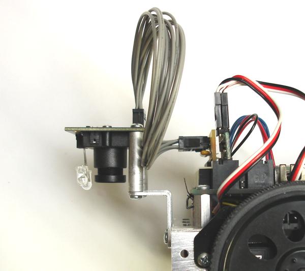
Next, mount the TSL1401-DB to the BOE-Bot using the L-shaped brackets and standoffs, as shown in the photos below:


Then, plug the DB-Expander into the solderless breadboard and wire to Vdd, Vss, and P0-P3 as shown here:

Here's a chart to summarize the connections (DB-Expander pinouts -> BOE pinouts):
Plug the ServoPAL into servo headers 12-13. Connect the right-hand servo to the forward ServoPAL header; the left-hand servo, to the rear ServoPAL header.
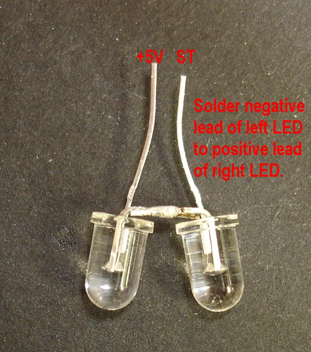
Now, enter the tsl1401_follower.BS2 program (attached below) into your BASIC Stamp II. Before running this code to follow a line, flip the BOE-Bot's power switch momentarily into the #2 position, then back to #1. You should see the LEDs flashing on and off. Position the BOE Bot over a white sheet of paper, and adjust the LEDs so that they illuminate a wide swath directly under the TSL1401-DB's lens as evenly as possible.
Now you're ready to try line following. I used 1/2" flat black crepe masking tape available from McMaster-Carr (#76265A41). 3/4" electrical tape may also work, but you should adjust the line constant to 16 for best results. Lay out a track on light-colored flooring, and give it a whirl. You can view a video of my results here:
····www.phipi.com/redeye/redeye_video.wmv
(NOTE: Because of the low frame rate, the constant flashing of the LEDs looks rather more sporadic in the video. Also note that the patterned floor does not affect performance.)
-Phil
Post Edited (Phil Pilgrim (PhiPi)) : 5/28/2010 5:26:03 AM GMT
For this project, you will need the following:
- 1 ea. BOE-Bot
- 1 ea. TSL1401-DB Linescan Sensor
- 1 ea. DB-Expander
- 1 ea. DB Extension Cable
- 1 ea. ServoPAL
- 2 ea. L-shaped Mounting Brackets
- 2 ea. Round Standoff 4/40, 1 in.
- 4 ea. Panhead screw, 4/40, 1/4
- 2 ea. 5mm Wide-Angle Red LED (RadioShack #276-309)
- 1 ea. 75-ohm resistor
Next, mount the TSL1401-DB to the BOE-Bot using the L-shaped brackets and standoffs, as shown in the photos below:
Then, plug the DB-Expander into the solderless breadboard and wire to Vdd, Vss, and P0-P3 as shown here:
Here's a chart to summarize the connections (DB-Expander pinouts -> BOE pinouts):
- +5V -> Vdd
- Vdd -> Vdd
- A -> P0
- B -> P1
- C -> P2
- D -> P3 (IMPORTANT: Make this connection with a 75-ohm resistor, not with the blue wire shown in the photo.)
- Gnd -> Vss
Plug the ServoPAL into servo headers 12-13. Connect the right-hand servo to the forward ServoPAL header; the left-hand servo, to the rear ServoPAL header.
Now, enter the tsl1401_follower.BS2 program (attached below) into your BASIC Stamp II. Before running this code to follow a line, flip the BOE-Bot's power switch momentarily into the #2 position, then back to #1. You should see the LEDs flashing on and off. Position the BOE Bot over a white sheet of paper, and adjust the LEDs so that they illuminate a wide swath directly under the TSL1401-DB's lens as evenly as possible.
Now you're ready to try line following. I used 1/2" flat black crepe masking tape available from McMaster-Carr (#76265A41). 3/4" electrical tape may also work, but you should adjust the line constant to 16 for best results. Lay out a track on light-colored flooring, and give it a whirl. You can view a video of my results here:
····www.phipi.com/redeye/redeye_video.wmv
(NOTE: Because of the low frame rate, the constant flashing of the LEDs looks rather more sporadic in the video. Also note that the patterned floor does not affect performance.)
-Phil
Post Edited (Phil Pilgrim (PhiPi)) : 5/28/2010 5:26:03 AM GMT
606 x 685 - 93K
600 x 533 - 43K

755 x 561 - 63K

695 x 472 - 76K

Comments
▔▔▔▔▔▔▔▔▔▔▔▔▔▔▔▔▔▔▔▔▔▔▔▔
Whit+
"We keep moving forward, opening new doors, and doing new things, because we're curious and curiosity keeps leading us down new paths." - Walt Disney
thanks for sharing the really great information and illustration.
jim
▔▔▔▔▔▔▔▔▔▔▔▔▔▔▔▔▔▔▔▔▔▔▔▔
The smarter I get, the more I understand I don't know!
Could you expliain the algorithm used to detect the line?
I'm using this sensor with a freescale microcontroller but I don't know how to detect the line.
-Phil
▔▔▔▔▔▔▔▔▔▔▔▔▔▔▔▔▔▔▔▔▔▔▔▔
···································Fix it, if ain't broke!
D Rat
Dave Ratcliff N6YEE
Regarding the "tires": those are actually rubber lens focus rings that I got years ago from Universe Kogaku. With a bit of stretching, they fit the BOE Bot wheels perfectly, although there is some lateral slippage. I really ought to glue them on.
-Phil
▔▔▔▔▔▔▔▔▔▔▔▔▔▔▔▔▔▔▔▔▔▔▔▔
···································Fix it, if ain't broke!
D Rat
Dave Ratcliff N6YEE
1. Read each pixel from sensor and then you use the A/D converter of the microcontroller and storage the information (1 or 0) in an array.
2. Compute the average (this part is sort of confusing????)
3. Accomplish a control action.
I'm sorry I'm a newbie but, I will appreciate your help. Thanks.
-Phil
-Phil
http://www.taosinc.com/Productfamily.aspx?id=3&SD=lsa
-Phil
Change it to read:
-Phil
Any advice is appreciated
Thanks
-Phil
-Phil
Hey man i got another question for you. So im trying to get the bot to follow a black line on a white board, and then switching to a white line on a black board. I have the program broken down to make the bot do that. now i trying to get the bot to follow the black/white line, then using a whisker to sense a barrier that will in turn control a seesaw mechanism. i think i need to rework the program because i cannot figure out how to get the bot to stop line scanning/moving to do the other operation. I also am wondering if the speed is being held back because the program is constantly checking if it needs to run the white on black or black on white line scan. i think i need to figure out how to change the WHICH CON LIGHT to WHICH CON DARK depending on the CNT variable. Not only do i want the bot to be able to change from dark line on white background to black line on dark program, but i also want to have other mechanical operations during the line scan. let me know what you think..
thanks
Here's the source code and the BS2 functions used in the port of Phil's code:
tsl1401_follower.spin
BS2_Functions.spin
When porting PBasic watch out for the order of operations and the operators >= and <=. Holy smoke did that cost me some time.
Im a real newbie and I want to understand the code on the first page,
You set the constant line on a ½ but how do you get to that number?
You shift 22 >> 1 so that means 11 = ½ en above the program you said 16 = ¾
But how do you get to the these numbers?
22? 11= ½ and 16=3/4.
If there is someone who can answer this question I would be great full.
Leroy
But I do know exactly how I missed your original November 2009 post. My twins were born October 2009 and I was a sleep-deprived zombie for a year.
Really neat. I'm about to use this sensor for the first time and your fine work is an excellent starting place, much obliged. This padawan has much to learn from Jedi PhiPi. Unlearn the relay ways I have learned, I must.
In my case my kids were born in 2000 and 2002, but only 22 months apart. So my wife and I spent almost three years as sleep-deprived zombies. I really don't remember anything between 2000 to 2003.