

LM358 problem
 rjo_
Posts: 1,825
rjo_
Posts: 1,825
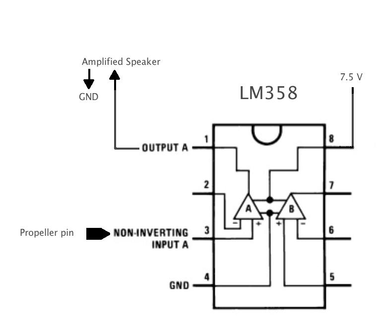
If I generate an audio signal and send it straight from my prop to an amplified speaker... I hear it loud and clear.
But when I send it through an lm358 as in the picture... it is barely audible. Why?
But when I send it through an lm358 as in the picture... it is barely audible. Why?
764 x 652 - 26K
Comments
a LM358 is not a plug&play chip.
You need some additional components to configure the function and the gain-factor
The most simply circuit is shown in this datasheet on page 7
Anyway you can't get much current out of the LM358. This chip can only drive a very small loudspeaker (2 inch 0,1 Watt)
For really amplifing you will need a transistor-stage.
best regards
Stefan
-Phil
http://www.eng.yale.edu/ee-labs/morse/compo/sloa058.pdf
line-level input) and further that when driven by a prop pin, it works fine.
In any case, yes, if you're going to use an LM358 you'll need at least some feedback
components. Your op amp is probably ringing all over the place.
How did you expect it to work in that (un)configuration?
Ok, this is a way you could use the LM358 for buffering to line levels.
R18 + C14 form the RC DAC from the Prop pin
R30 + R34 form the voltage divider to reduce the level to around 1V p-p (audio line levels)
R31 biases the signal to around 2V to keep the LM358 from clipping.
C25 is a bit of optional extra filtering
R20 + C17 provide a filtered bias supply otherwise noise would be coupled directly from the noisy supply straight through.
L2, C19 are optional
C16 provides AC coupling to remove an DC bias and in case the "load" is assuming it is AC coupled.
Simpler than that?
Ok, you could do it with the LM358 and R18 and C14 like in the second shot and not worry about all the biasing and AC coupling.
BTW, don't leave the other pins just dangling, it's still an active circuit and will be causing problems. Tie pin 6 & 7 together and pin 5 to ground.
▔▔▔▔▔▔▔▔▔▔▔▔▔▔▔▔▔▔▔▔▔▔▔▔
*Peter*
Now, having said that, the Prop should be able to drive an amplified speaker (which presumably has "line-level" inputs) directly — no external amp required.
-Phil
Methinks however that the poor chap has been running the Prop pin straight into the amplifier ( ye gads!) and the ampliFRYER has obliged and filtered it due to it's own limitations features. But yes, if he has an RC DAC he can feed it directly.
▔▔▔▔▔▔▔▔▔▔▔▔▔▔▔▔▔▔▔▔▔▔▔▔
*Peter*
This is all Ray Allen's fault[noparse]:)[/noparse] http://rayslogic.com/propeller/Programming/PropEKG/circuit.png
Ray provides complete info and the files to make your own PCB if you want. I took one look at the schematic and didn't have a clue what the circuit was doing... and I didn't have the right parts. See pic 1.
That got me looking around and I found a minimalist approach that seemed within my comprehension... see pictures 2 and 3 by Scott Harden at swharden.com/
One goal is to use the EKG wave to trigger a camera, but there are a variety of other uses for this basic functionality.
I have a nice tome about OPAMPs but haven't had time to read it yet.
I re-read the datasheet... looking for the right current spec and Phil is right at 7.5 volts there isn't much power available.
But I think there might be something else happening to my signal.
I have a lm386... so that is the next step.
You guys are wonderful.
Rich
BTW, I knew that you knew what you were doing so it's great when we can blame someone else hey! That Ray Allen ^%$*$@^!!
▔▔▔▔▔▔▔▔▔▔▔▔▔▔▔▔▔▔▔▔▔▔▔▔
*Peter*
The op-amp in the original drawing was missing the feedback connection from (-) to (output). Blue line in the attached. With that connection it is a x1 gain buffer, and it should pass the signal almost unaffected to the amplified speaker. Without that connection, the inverting input is floating and any signal that gets through to the output is an accident. The x1 buffer is a useful circuit, but you can see that there are plenty of more complicated arrangements you can use to shape the response.
▔▔▔▔▔▔▔▔▔▔▔▔▔▔▔▔▔▔▔▔▔▔▔▔
Tracy Allen
www.emesystems.com
Most of my experience is with EMG (Electromyography), but the principle is basically the same for ECG.
For picking off an ECG or EMG signal you really need to use an instrumentation amplifier. The 'third' electrode should not be grounded at all. Instead, the third electrode should be the common mode voltage between both of the input electrodes. This way you increase your signal to noise ratio with dynamic filtering leaving you a cleaner signal on the output. For ECG or EMG, you still need to filter 50/60 Hz depending on what your local power grid is because it will swamp your signal with the amount of gain you will need in order to detect the signal. For ECG, since the signal that you are interested in is below 50/60 Hz (the heartbeat) it may become difficult to isolate it from the 50/60Hz with a simple filter circuit, where on the other hand EMG has frequency components above 50/60 Hz that are beneficial making a high-pass filter set to about 200Hz all that you really need.
▔▔▔▔▔▔▔▔▔▔▔▔▔▔▔▔▔▔▔▔▔▔▔▔
Beau Schwabe
IC Layout Engineer
Parallax, Inc.
Leon
▔▔▔▔▔▔▔▔▔▔▔▔▔▔▔▔▔▔▔▔▔▔▔▔
Amateur radio callsign: G1HSM
Suzuki SV1000S motorcycle
True, however EMG is usually battery powered.... i.e. used in a prosthetic arm.
▔▔▔▔▔▔▔▔▔▔▔▔▔▔▔▔▔▔▔▔▔▔▔▔
Beau Schwabe
IC Layout Engineer
Parallax, Inc.