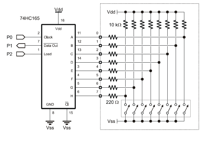
74HC165 for pushbutton input expansion
I copied out the attached 74HC165 input expander circuit·to give myself more inputs then realized I was using momentary contact switches.
With the discussion about switch de-bounce etc. I was wondering if this circuit would·reliability record and latch the button pushes until my program·came around and read them.
With the discussion about switch de-bounce etc. I was wondering if this circuit would·reliability record and latch the button pushes until my program·came around and read them.


Comments
What you can do to minimize the problem is to always read all your '165 switches in a tight loop. Save that status as a byte or word then process each bit one at a time through your program.
Then, repeat.
If your momentary switches are opening and closing faster than the Stamp program scans, you'll have to add some front end latches.
Cheers
▔▔▔▔▔▔▔▔▔▔▔▔▔▔▔▔▔▔▔▔▔▔▔▔
Tom Sisk
http://www.siskconsult.com
·
▔▔▔▔▔▔▔▔▔▔▔▔▔▔▔▔▔▔▔▔▔▔▔▔
Don't worry. Be happy
-Jeff
The difference from HIGH to LOW when the switch closes is 5V to 1.4V (assuming TTL levels) which is 3.6V. When the output reaches 1.4V the input will be a logic LOW.
It then takes t = -1 x R1 x C1 x ln(voltage difference)
Which is t = -1 x 1000 x 0.0001 x -1.27 = 0.13 seconds
When the switch opens, the delay i approx the same. Use a larger resistor and/or capacitor to lengthen time. The resistor should be well below the 10K pullup (or the line won't go low).
▔▔▔▔▔▔▔▔▔▔▔▔▔▔▔▔▔▔▔▔▔▔▔▔
Don't worry. Be happy
▔▔▔▔▔▔▔▔▔▔▔▔▔▔▔▔▔▔▔▔▔▔▔▔
Don't worry. Be happy