

Memsic 2125 Accelerometer question...
 Beau Schwabe
Posts: 6,547
Beau Schwabe
Posts: 6,547
This question is purely for academic exercise...
If you took two accelerometers mounted on the same plane with one of them oriented 180 deg about the Z axis. What would you be left with after mathematically cancelling out acceleration between them? Would you have usable inclination results impervious to motion? Years ago I proved that you could derive angular rate looking at the difference between the two sensors that were in the same orientation, but at the time I didn't think to flip one around 180 Deg from the other.
Comments
I have just the platform to test.
Here is one on a breadboard mounted in my G scale caboose.
I was actually wondering if I can determine if the caboose turns left or right using a single memsic, and i should be able to the way I have it laid in the image.
But I didn't think about inclination, which would help me with my hills, see I cannot have steep rail, i don't have super heavy engines with multiple drive trucks.
And sometimes its hard to see a deviation in the incline, other than the engine will slow, and sometimes stop if I have too many cars.
Great now I need to order another 2125.
You can see what I do with a single memsic to determine if the caboose is moving, I then take that info and feed it via a wx module to the engine,
and if no movement is found, the engine stops.
Its the caboose.spin file in the zip at this post, and i think it even uses your example code!
https://forums.parallax.com/discussion/comment/1521627/#Comment_1521627
The caboose getting inclination data for the engine is a bit late, but doing this in the engine.. now that is an idea...
I can see the motor amperage use increase on an incline, in the FB line on the parallax dual motor controller output fed into an activity board A2D.
You can see it works pretty well, but that is a fairly poor way to determine incline, since wind, track condition and other factors can cause amperage increase/decrease.
But knowing the incline at the moment the engine hits it, could possibly help with speed regulation at speeds less than max pwm.
I can wire up another one in the caboose, but doing what you said in code ... i am not even sure where to start.
I just know that I had to average the memsic readings to get a more stable result, even at rest it buzzes.
apparently g scale rails are not smooth, at all, nor flat, then the tie gap between the rails adds even more fun.
The inclination could be plotted live like I did with the parallax dual motor drive's FB output.
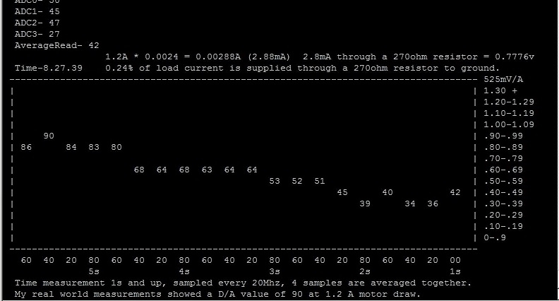
This image is a live plot of the motor draw when the train is going down a hill.
The inclination would show here also, and could be an additional variable for a PID.
So far I only have the motor draw FB, I don't even have axle rotation sensor, I need to get a hall sensor.
Keep me posted and I'll do the same ... I have a few sensors to play with in the mail that should be here in a day or so, as well as a $$$ IMU to play with that I can compare results against.
As far as the code, apply the difference between the RAW pulse width of the 2125's before actually deriving any acceleration data. <-- I'll have to look at this, it has been several years. But I plan on measuring the pulse width of each sensor with a high speed counter (could be propeller, maybe not) it is important however that the accelerometers are measured at the same time and NOT one right after the other.
Just a quick update ...
I think we are going with the IMU module because of it's ease to communicate with and the time frame we have with our client to complete the project. I could finagle a couple of other accelerometers together and derive an inclination function (I think) but the IMU does it already and is impervious to any acceleration while still providing a true tilt angle to 1/10th of a degree.
So you are basically thinking of doing a two axis of this?
https://www.parallax.com/product/gyroscope-module-3-axis-l3g4200d/
Using two memsic?
WTF, 20$ off that product?
Gyroscope Module 3-Axis L3G4200D
SKU 27911
$29.99 $9.87
535 in stock
@"Clock Loop" - That price is a steal, but that sensor doesn't quite do what I am after. The "angular Rate" means that if you stop moving the value will eventually return back to the noise floor. I need it to hold the Angle the sensor is sitting at.
The IMU that we are using is from WitMotion and will hold an angle to within 0.1 Deg even during acceleration without affecting the angle output.
Oh, I didn't see that it was a rate, now I am even more interested in what you are talking about with the memsic devices.
And I also now get what you are talking about with the memsic and their differential.
So you are talking about using two memsic to eliminate acceleration?
Ok, I see now, their values will change equally at acceleration, but if you flip one, ....
I can't visualize it, id need to draw it out. I can't brain how you can get angle with/without acceleration
This WOULD be interesting to play with, but getting it to be within 0.1deg like your IMU..
I think the floor noise of the memsic device might be a problem, since the noise is nonuniform between two devices?
But getting some info out of it would be possible.
Two memsic's are 60$, but that IMU is also around the same price.'
I guess if I had two memsic devices, id try it...
I see why you say for academic purposes, it makes no sense otherwise. price/accuracy
Thinking about it, does it matter if the second one is rotated in any specific direction?
180 deg about the Z axishurmph..
And now you are giving me a headache as i think about it with my hands.
Ok I conclude that you can do it with one the same as two, and its all done by taking measurements at rest/not/angle/not.>
And you need to keep track of the into in a database, so then does that say that no you cannot do this?
If were talking raw info from the sensor at that moment with no database history to compare?
Then no I conclude you can't do it.
But then i visualize
Two devices moving forward on a flat plane.
Two devices standing still on an incline.
Then two devices moving forward on an incline.
Then two devices moving forward on an incline, while turning to the left. (like up a spiral)
And my brain farted. Good BYTE.
@"Beau Schwabe" said:
Enough with this academic brain farting, I think im gonna go dig a hole and hang out around it. That seems easy enough.
@"Clock Loop" - For NDA reasons I can't be more specific, other than the payload is 10 tons and it needs to be level at all times and there are times it will most likely be in motion and still needs to remain level. The actuators to move the payload are already defined and adequate.
Oh, you don't need to talk about your specifics. Lets talk about this memsic or two.
I found your other code in that memsic spin object, I never saw that you have some interesting things in there.
New goodies to play with.
I was adding graphing to my caboose telnet putty terminal debug, and I wondered how you did it all. So I opened it.
I should have done that a while ago, but alas, one can't get to all things they come across.
And im still thinking...
ok ok....
Now im going to play with those other pub subs you wrote!