

Cluso's MiniBlade2 - possible mini P2 1.0"x1.6" - any interest ???
 Cluso99
Posts: 18,069
Cluso99
Posts: 18,069
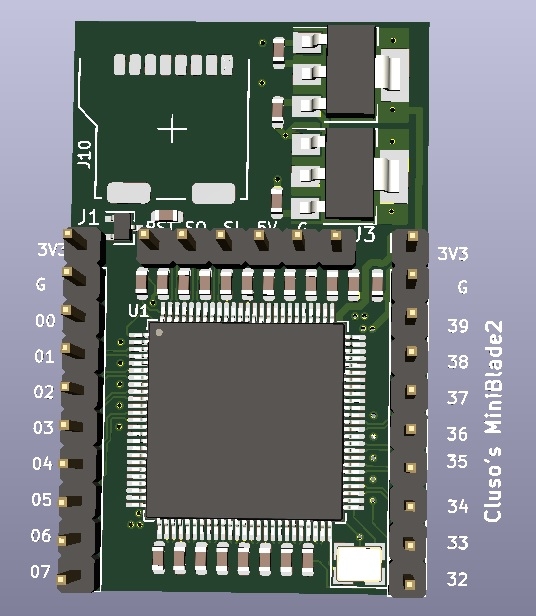
Here is a possible new P2 mini I've been working on...
Cluso's P2 MiniBlade2
* PCB 1.0"x1.6" 2 layer ENIG 1.0mm FR4 (note 1.0mm)
* P2X8C4M64P Rev C chip of course
* 20MHz xtal
* Requires 5V regulated input (from 0.1" USB/TTL header)
* 3V3 1A LDO SOT-223
* 1V8 1A LDO SOT-223 (fed from 3V3 regulator)
* Bulk and bypass capacitors (not as quiet as RetroBlade2 board)
* Transistor reset circuit (as per P1) (maybe without configured with solderable link)
* microSD socket (microSD card not supplied) - can boot direct from microSD without Flash
* P00-07 brought out on 1x10pin 0.1" header (with 3V3 and GND)
* P32-39 brought out on 1x10pin 0.1" header (with 3V3 and GND)
* P58-61 used internally for microSD and (optional) SPI Flash
* P62-63 brought out on 1x6 0.1" header (serial port) for Reset/SerialOut/SerialIn/5Vin/Gnd/nc - compatible with CP2102 USB-A/TTL 6pin (not supplied - fleabay ~$1.50)
- considering swapping 5V & GND to use the new CP2102 module with microUSB connector (uses different pinout ) - fleabay ~$1.50
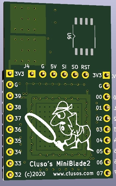
* Optional SOIC-8 (possible XSON8) footprint on underside for Flash W25Q32JVSIQ/W25Q64JVSIQ/W25Q128JVSIQ (4/8/16MB Flash)
* Through hole parts supplied but not fitted/soldered
* Price without flash USD $45 posted unregistered airmail from Australia
* Price with flash USD $50 unregistered airmail from Australia
* If there is enough group orders to the USA, I'm sure Publison will repost locally.
Notes:
* The regulators will likely self-limit to somewhere in excess of 500mA. Switchers are not used.
* The 3d image does not show the microSD connector (see photos of my RetroBlade2)
* A 1x2pin 0.050" header/link (solderable??) enables the 10K pullup resistor (fitted as standard) for booting from the (optional) Flash chip
This pcb is very tight and I haven't completed it yet. It's a tiny pcb with limited I/O. This required some limitation in how I can route the bulk and bypass capacitors and may therefore slightly compromise the ADC performance. Switchers are not used for the regulation and will therefore possibly limit overclocking and pushing the P2 to its' limits. IMHO this is an acceptable design limitation. I have a couple of ideas too.
One question...
The CP2102 now comes in two options on fleabay. The older one has a full size USB plug onboard, while the newer one has a microUSB socket. Unfortunately, they swapped the 5V and GND pins around. The newer board is smaller and nicer but my RetroBlade2 uses the older CP2102. The newer CP2102 also does not have the 0.1" pins soldered so that a socket could be fitted to this pcb, and male pins to the MiniBlade2. This would help prevent plugin errors if you have both. Do I swap to the newer pinout???
https://ebay.com/itm/MICRO-USB-to-UART-TTL-Module-6Pin-Serial-Converter-CP2102-STC-Replace-FT232-D/112049647905?hash=item1a16adf121:g:a~gAAOSwWdNcNq1W
Is there any interest if I proceed with making boards ???
Cluso's P2 MiniBlade2
* PCB 1.0"x1.6" 2 layer ENIG 1.0mm FR4 (note 1.0mm)
* P2X8C4M64P Rev C chip of course
* 20MHz xtal
* Requires 5V regulated input (from 0.1" USB/TTL header)
* 3V3 1A LDO SOT-223
* 1V8 1A LDO SOT-223 (fed from 3V3 regulator)
* Bulk and bypass capacitors (not as quiet as RetroBlade2 board)
* Transistor reset circuit (as per P1) (maybe without configured with solderable link)
* microSD socket (microSD card not supplied) - can boot direct from microSD without Flash
* P00-07 brought out on 1x10pin 0.1" header (with 3V3 and GND)
* P32-39 brought out on 1x10pin 0.1" header (with 3V3 and GND)
* P58-61 used internally for microSD and (optional) SPI Flash
* P62-63 brought out on 1x6 0.1" header (serial port) for Reset/SerialOut/SerialIn/5Vin/Gnd/nc - compatible with CP2102 USB-A/TTL 6pin (not supplied - fleabay ~$1.50)
- considering swapping 5V & GND to use the new CP2102 module with microUSB connector (uses different pinout
* Optional SOIC-8 (possible XSON8) footprint on underside for Flash W25Q32JVSIQ/W25Q64JVSIQ/W25Q128JVSIQ (4/8/16MB Flash)
* Through hole parts supplied but not fitted/soldered
* Price without flash USD $45 posted unregistered airmail from Australia
* Price with flash USD $50 unregistered airmail from Australia
* If there is enough group orders to the USA, I'm sure Publison will repost locally.
Notes:
* The regulators will likely self-limit to somewhere in excess of 500mA. Switchers are not used.
* The 3d image does not show the microSD connector (see photos of my RetroBlade2)
* A 1x2pin 0.050" header/link (solderable??) enables the 10K pullup resistor (fitted as standard) for booting from the (optional) Flash chip
This pcb is very tight and I haven't completed it yet. It's a tiny pcb with limited I/O. This required some limitation in how I can route the bulk and bypass capacitors and may therefore slightly compromise the ADC performance. Switchers are not used for the regulation and will therefore possibly limit overclocking and pushing the P2 to its' limits. IMHO this is an acceptable design limitation. I have a couple of ideas too.
One question...
The CP2102 now comes in two options on fleabay. The older one has a full size USB plug onboard, while the newer one has a microUSB socket. Unfortunately, they swapped the 5V and GND pins around. The newer board is smaller and nicer but my RetroBlade2 uses the older CP2102. The newer CP2102 also does not have the 0.1" pins soldered so that a socket could be fitted to this pcb, and male pins to the MiniBlade2. This would help prevent plugin errors if you have both. Do I swap to the newer pinout???
CP2102 older pinout 3V3, DTR, RXD, TXD, GND, +5V
CP2102 newer pinout      DTR, RXD TXD, +5V, GND, 3V3
https://ebay.com/itm/CP2102-USB-2-0-to-TTL-UART-Module-6Pin-Serial-Converter-STC-Replace-FT232-Part/183568878277?hash=item2abd8ecac5:g:M40AAOSwuQhcB3PW
https://ebay.com/itm/MICRO-USB-to-UART-TTL-Module-6Pin-Serial-Converter-CP2102-STC-Replace-FT232-D/112049647905?hash=item1a16adf121:g:a~gAAOSwWdNcNq1W
Is there any interest if I proceed with making boards ???
Comments
If you do make it, may I suggest a quality push-push style microSD socket?
Many of you know my interest in Z80/CPM emulations. My P1 RamBlade is considered the smallest CPM board - it fits in a matchbox and is 1.2”x1.9”. So I need a version that is smaller to claim an unofficial prize
Would it help if I say it’s impossible
The Switching ones are expanding in choice, and there are many BOM choices
* Cheapest switchers, adjustable need R/R/L - lowest price, but a bit more PCB area. (P2 Edge uses this choice)
* Fixed Voltage switchers, need external L, but integrate the divider.
* Integrated inductor switchers, some need R/R and some like Murata MYRGM180150B31RA have R/R/L all included.
The new MYRGM180150B31RA is 1.5A capable, and is 2.5mm×3.2mm, h=1.0mm
It may be possible to have a footprint choice for such a simple one-part switcher alternative ?
4 layers doesn't really give me anything.
Anyway, it's mostly done now. I'll consider whether I make it depending on interest and my own thoughts over xmas.
For my RetroBlade2...
At idle and downloading (115,200 baud) draws under 50mA
Running my OS at
200MHz draws 230mA
300MHz draws 265mA (not working as there are currently other things that also need adjusting)
360MHz takes 275mA (not working)
These figures will increase as my OS takes shape.
Running my Z80/CPM
200 MHz draws 220mA
This would be 3.4" long, so how wide to support it???
The biggest problem may be the P2 chip which can be too big (16x16 mm?) to place it on such a board and provide space needed for all needed connections without using a multilayer board. Standard DIP64 chip is 0.8" wide. A board with pins underside should be something like 3.4..3.5x1.0..1.2" ... ~90x30 mm.
Still like to get COBOL-Z80 running. It fails on the ramblade CP/M.
Mike
Your RamBlade microSD will work for my P2 Z80/CPM as i use the same cpm files. I share the same microSD card between P1 and P2
Give cobol a try as my z80 is based on pullmoll’s z80 base code rather than heaters ZiCog. No promises. If it doesn’t run then i am after help to run zexall to find any problems.