

P2 PLL clock setup documentation question
 rogloh
Posts: 5,170
rogloh
Posts: 5,170
I'm making some PLL changes in my video driver and saw this in the SPIN2 document but wonder if it is correct.
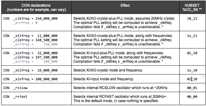
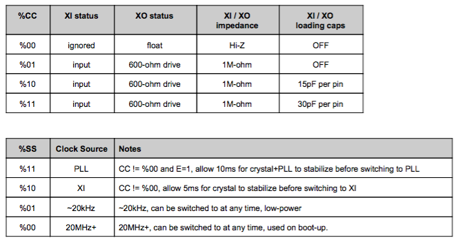
In the third case in this table with both the PLL and the direct clock input XI (no crystal) in use, should the CC_SS bits be %01_10 or should they be %01_11 to make use of the PLL as the clock source? Other information I found is shown below, but it still isn't clear. Why would we select %10 for %SS as the clock source if the PLL is being used as the source, or does the %SS=%10 also let you enable the PLL as the clock source but just disables the internal oscillator for the crystal? Maybe this documentation is incorrect or incomplete, or I am just reading it wrong.
In the third case in this table with both the PLL and the direct clock input XI (no crystal) in use, should the CC_SS bits be %01_10 or should they be %01_11 to make use of the PLL as the clock source? Other information I found is shown below, but it still isn't clear. Why would we select %10 for %SS as the clock source if the PLL is being used as the source, or does the %SS=%10 also let you enable the PLL as the clock source but just disables the internal oscillator for the crystal? Maybe this documentation is incorrect or incomplete, or I am just reading it wrong.
Comments
So what happens in SPIN2 when a nested driver COG tries to make use of these _xtlfreq or _xinfreq names when they might already not be setup by the top level file? Are they still available to compile in but are set to zero, or will they default to 20MHz, when unspecified for example? I'm trying to figure out if my code can even use them when changing the PLL.
My current code looks like this but it would be nice to tidy it up and somehow make it automatic and not need changing based on the board setup if it could be obtained from the top level SPIN file clock information.
CON #0, CLKSRC_XTAL, CLKSRC_XIN ' select one of these based on your HW 'CLKIN_HZ = _xtalfreq 'CLKIN_HZ = _xinfreq CLKIN_HZ = 20000000 ' 20MHz default CLOCKSRC = CLKSRC_XTAL ' enable for crystal 'CLOCKSRC = CLKSRC_XIN ' enable for direct clock in (no crystal) PUB computeClockMode(desiredHz) : mode '<snip> ' final clock mode format is this #%0000_000E_DDDD_DDMM_MMMM_MMMM_PPPP_CCSS if mode ' also set 15 or 30pF capacitor loading based on input crystal frequency mode |= (1<<24) ' enable PLL if (CLOCKSRC == CLKSRC_XTAL) ' enable oscillator and caps for crystal mode |= (CLKIN_HZ < 16000000) ? %1111 : %1011 else mode |= %0111 ' don't enable oscillatorEDIT: Oh, the description talks about PLL. Hmm, yeah, could do with some editing. The fifth entry is the mode I was thinking of.
EDIT2: The first entry of the table is also extraneous as it is covered by the second entry.