

P2 NTSC/PAL video input
 SaucySoliton
Posts: 487
SaucySoliton
Posts: 487
in Propeller 2
I want your input to guide future development.
1. What kind of applications would you do with a video input?
2. NTSC or PAL?
3. bt.601 or square pixels?
4. Output resolution and color encoding?
5. High frame rate or reduced cog count?
Comments:
3. bt.601 is 720x480 for NTSC, 720x576 for PAL,
Square pixel is 640x480 for NTSC, 768x576 for PAL
Minimum clock frequency is 234 for bt.601, 221 for sqNTSC, 266 for sqPAL.
I would favor square pixels for machine vision applications.
4. Memory usage is a big concern here.
768x576x8bpp=442,368 bytes.
720x480x8bpp=345,600 bytes.
640x360x16bpp=460,800 bytes.
384x288x16bpp=221,184 bytes.
320x240x32bpp=307,200 bytes.
320x240x24bpp=230,400 bytes.
320x240x16bpp=153,600 bytes.
YCrCb output would save a few clock cycles.
5. Capturing the monochrome video almost totally utilizes 1 cog. I estimate at least 2 additional cogs to decode color in realtime. The capture cog could stop after capturing a frame and convert the output to color.
Based on the above I think I would want 320x240 output for color to allow the possibility of 2 images in memory. 1 for capture, 1 for processing. Higher resolutions just don't make much sense except for really simple algorithms. The capture code operates at 9 instructions/pixel and getting 12 instructions/pixel requires a sysclock over 300MHz.
Here's a test image. It's NTSC, with bt.601 sampling, but with 48 additional pixels on the left side. That's to get some of the color burst. It's a single ADC pin, using the Goertzel hardware for the window filter. Sampling is line-locked, controlled by the Goertzel NCO.
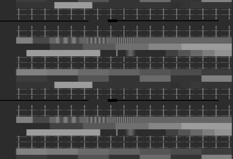
Code is attached. It's alpha quality, beware. Horizontal sync is not optimal. Vertical sync is non-existent.
1. What kind of applications would you do with a video input?
2. NTSC or PAL?
3. bt.601 or square pixels?
4. Output resolution and color encoding?
5. High frame rate or reduced cog count?
Comments:
3. bt.601 is 720x480 for NTSC, 720x576 for PAL,
Square pixel is 640x480 for NTSC, 768x576 for PAL
Minimum clock frequency is 234 for bt.601, 221 for sqNTSC, 266 for sqPAL.
I would favor square pixels for machine vision applications.
4. Memory usage is a big concern here.
768x576x8bpp=442,368 bytes.
720x480x8bpp=345,600 bytes.
640x360x16bpp=460,800 bytes.
384x288x16bpp=221,184 bytes.
320x240x32bpp=307,200 bytes.
320x240x24bpp=230,400 bytes.
320x240x16bpp=153,600 bytes.
YCrCb output would save a few clock cycles.
5. Capturing the monochrome video almost totally utilizes 1 cog. I estimate at least 2 additional cogs to decode color in realtime. The capture cog could stop after capturing a frame and convert the output to color.
Based on the above I think I would want 320x240 output for color to allow the possibility of 2 images in memory. 1 for capture, 1 for processing. Higher resolutions just don't make much sense except for really simple algorithms. The capture code operates at 9 instructions/pixel and getting 12 instructions/pixel requires a sysclock over 300MHz.
Here's a test image. It's NTSC, with bt.601 sampling, but with 48 additional pixels on the left side. That's to get some of the color burst. It's a single ADC pin, using the Goertzel hardware for the window filter. Sampling is line-locked, controlled by the Goertzel NCO.
Code is attached. It's alpha quality, beware. Horizontal sync is not optimal. Vertical sync is non-existent.
Comments
Frankly, I am with you on the basics for machine vision and related apps. Square pixels and a modest memory footprint should open up some interesting work.
If it is not too much trouble, developing with the option for bt601 may have uses. People could choose. I am interested in both. At the least, those interested could learn more and roll their own.
This on the 2a chip right?
It is a 2a chip. The 2b should be a little better if using multiple ADCs in parallel. The 2b scope filter could also be used, but it doesn't have the capability to interpolate between samples. There would be some jitter as the streamer is forced to quantize the sample time to a sysclock step. Although would 5 degrees of jitter be noticeable?
The attached plots are from a multiburst test signal. Looks like the attenuation is not that bad. Although it would be neat to compensate it with a passive pre-emphasis circuit.
2. NTSC
3. Don't care. If non-square pixels, you can reduce the geometry with a look-up table.
4. If you go for the highest resolution possible, you can always subsample to put an image into memory or on the screen.
With higher resolution you can sample just part of the image... several lines for instance... to get better
measurements.
5. Highest frame rate possible with monochrome images.
Your code is mostly beyond me at this point. For example, you are getting at least 169 levels of gray from a 128 sample LUT... unless some of that comes from an image initially read into the LUT in Cog0?
It looks like you are capturing two complete fields at greater than 7 bits.
But it also looks like you are only getting about half the data from each field?
The good data looks really good... So, what you have is already useful.
2. ideally both, but NTSC seems more common. ideally also nonstandard signal types, such as NTSC50/PAL60 and 240p
3. ideally adjustable horizontal res.
4. YCbCr is fine I guess
5. In this case, high frame rate.
It says "effective resolution 976x494." So 482,144 pixels. Now getting that many pixels out of NTSC video will require an 18.56MHz sample rate. That means a clock rate of 335MHz. Maybe we could reduce it to 297MHz by removing some features from the code.
The LUT contents are used as weights for the incoming bits from the ADC. It was originally intended for the weights to be sine and cosine for Goertzel measurements. I'm using triangular ramps, which I tried to explain here: forums.parallax.com/discussion/comment/1476671/#Comment_1476671 The streamer steps though the LUT at a pre-programmed speed. It is acceptable and useful to step by more than one address at a time. I use the ramp up and ramp down to break the continuous ADC stream into discrete samples. There is some overlap where the weights for one sample decrease while the weights for the next sample increase. To increase the sample rate, one would ramp up and ramp down quicker. What I consider beautiful and elegant is that breaking of the ADC stream into samples can be done at any arbitrary rate. The code adjusts the sample rate to get exactly 858 samples per line.
Since the sample rate can be adjusted to almost anything, it would be best to just sample according to the number of pixels we want. Although for color video that forces a certain minimum sampling rate, so there would be a reason to subsample by 2 or some other easy factor.
There is no vertical sync yet. You are seeing bottom of one field, one complete field, and the top of the next field.
Tomorrow.
---
Also more options sampling at 4x the subcarrier.
NTSC 753x480 @ 258MHz
PAL 922x576 @ 320MHz
Even if the camera is color only, we could get monochrome output with a comb filter. It's just averaging a few adjacent lines, so fast to run but likely to need its own cog. I did some tests with a comb filter on the captured data. The luma output looks great. The chroma, well there's a lot cross-color rainbows on the edges.
Or just lowpass to remove the color carrier, but then we loose a lot of resolution.
Saucy is right though. The comb can deliver pretty great monochrome. A cutoff = about 320 pixels tops, and 160 if it's severe.
3. bt.601 is 720x480 for NTSC, 720x576 for PAL,
Square pixel is 640x480 for NTSC, 768x576 for PAL
It is a 4/3 square picture, all the actual camera's are 16/9 letterbox
=1920 pixels wide and 1080 pixels high.
We can take just a part of it for sample.
Can't we do hdmi in, it is already digital ?
It would be pretty tricky to get HDMI digital in at SD video resolutions, but perhaps not impossible if the streamer can first accumulate multiple bit samples into each long before transferring to hub. You could probably use the 27MHz HDMI clock as the P2 clock source and multiply by 10.
You'd have to sample the 3 bits (R/G/B) at 270MHz precisely aligned with the incoming HDMI clock for reliable transfer, and stream all of it into HUB, then have some COG searching for a start of the 10b code of one channel to find the right offset so it can begin to convert back to RGB pixel values using 10b to 8b reverse table on the accumulated bit values over 10 samples. The table could be in LUTRAM if only 9bits are used for its index. But the biggest problems is that you'd only get 5 instructions per pixel which is not much. The FIFO might keep you fed with data and you could probably extract each 10b symbol, but in the end you need time to do a RDLUT and then write a byte back to memory - or do some writes in the horizontal blanking. Seems to me you'd need lots and lots of COGs in parallel to have any hope at all, if there even is a way.
This would be a very challenging project to attempt. Getting the sample timing nicely phase aligned with the data could be an issue too.
So, if you have a need, current estimates for a revB reliable max clock rate is 360 MHz.
PS: I still want to test this under heavy load, so it might be revised down ...
Color decoding happens on the PC right now. It makes development much easier, especially since the P2 doesn't have enough memory for a full resolution, full color image.
One would have HUB space for two of the buffer/cameras and still have space for other code to run.
Anyway way cool what you are doing here,
Mike
I'm still thinking about what is the best way to do video capture.
Goertzel mode: This is what I used on RevA. The RevB has a nice improvement from adding multiple ADCs together in parallel. But this code uses Goertzel mode in a way that the hardware was not designed for. The problem is that the sinc2 mode for Goertzel added a clock delay to the output. I can compensate for this partially, but not completely. Because the video sampling rate is not an integer division of sysclock, the number of clocks between NCO overflows varies. The compensation offset is fixed. It's especially frustrating because I helped promote sinc on Goertzel. Nevertheless, RevB with a few ADCs in parallel should still be better.
Scope mode: This is non-optimal with regards to sampling time. The samples must be quantized to the nearest clock cycle. The time uncertainty is a few degrees worth at the colorburst frequency. A lot easier to program. Easier to support s-video/component/RGB. Harder to run parallel ADCs, the time to sum bytes together is not insignificant. Maybe it would be insignificant compared to color decoding. Since the streamer writes to hub ram, it is more difficult for the sampling cog to process the captured samples.
2/25/2020 I made some decisions
The decision is obvious: scope mode is the way to go. The Goertzel mode code must process the samples as they come in. This results in unrolled loops of code with 9 instruction blocks. About 8 of them are dedicated to processing pixel data. Then, the sync detection instructions can be inserted in the gaps. A total nightmare and perplexing to almost everyone who reads the original code above. The only possible advantage was better efficiency when using 4 adcs in parallel. At 2 adcs in parallel, they are roughly equal.
In scope mode, the streamer handles collecting the samples and writing them to the hub. The thing is, the streamer writes to hub ram, but I want the data in cog ram. So block move it is (fifo in use.) The streamer only writes 1 long every 21 clocks, so there is lots of bandwidth available. Scope mode can buffer several lines of video for processing. I can display the sync interval if desired, since it is in the buffer. I can skip from sync to active video, instead of waiting for video data to become available. Most importantly the code will be much easier to write.
Other things I decided:
Square pixel mode. It seems like non-square pixels would just frustrate any processing a user would want to do on acquired images.
Performance before quality. The P2 is probably not the processor of choice for broadcast quality video. But I think a lot of people would be surprised about how good the video quality from a single P2 pin is. I was. This guideline affects mostly the color decoding. Color decoding can get quite complicated for the best quality. So this means, chroma trap, not comb filter. No remodulation. YUV decoding instead of YIQ. Also shorter filter windows. The output from my simulations still looks pretty good.
Going to prioritize 320x240 output. I think it would be a cool demo to decode 4 signals and display them side by side. Shows off the excellent ADCs and also that it has enough power do 4 signals simultaneously.
The bits you showed off on Rev A were impressive.
Your decisions make good sense, and should still prove useful. And, if it is more sane, people can modify, improve.
A full frame, like "underscan" mode on many PVM displays may prove useful to others. I personally am more interested in the active region.
There's a bunch of solutions based on fpgas and line doubling and stuff, generally in the $100+ range.
http://junkerhq.net/xrgb/index.php?title=OSSC
This is the current 'state of the art', which most of the current retrogaming youtubers make use of.
It does various scaling modes including a very nice 5:4 "square pixel" mode on 1080p.
If the P2+HyperRAM can get the BoM down under $45, that could be the 'killer app' / 'the demo' that would have tens to hundreds of youtubers drooling over this chip with.
Have you considered trying S-Video, since the chrominance is split from the luminance?
Cool device! I don't know if the P2 could replace an FPGA based system like that. But I suppose since video decoding is the main application here it would be fine to have 3-4 cogs churning away to decode color video.
I will try S-Video. But that will be for video quality reasons. I wouldn't expect much difference in the time performance. With the right filter coefficients, a chroma trap is not costly. The rest of the chroma decoding is unchanged.
Do you really think there are enough people that would be excited if the P2 can halve or quarter the bom cost for a scan converter?
I added HDMI output so you can use the AV board for your video input. The resolution is 784x525 so it might not work everywhere. VGA output is 800x600, with the 784x525 letterboxed.
Sorry, NTSC only right now.
Edit: I've only tested this with fastspin.
Line frequency 25Khz. 34.5uS active video per line.
1944? active lines, 2000 lines total, 12.5 frames per seconds progressive scan
With the restricted bandwidth of the P2 adc and scope filter, we probably won't get any more horizontal pixels than from standard analog video. And due to the shorter active interval we could get less pixels. Getting all of the vertical pixels is no problem. But due to memory constraints, I can display only 1 out of 4 lines. The picture quality of this image is comparable to what the P2 does receiving NTSC video.
Update: Just scrolled up and saw the original pictures at the top, is that quality still about the same?
Hopefully the HyperRAM should be able to help you store larger images once it's out.
Superimpose computer image over Video. Like a Bluebox or Greenbox.