

Comparator mode testing
 ozpropdev
Posts: 2,791
ozpropdev
Posts: 2,791
Chip
I've been testing the comparator modes in P2 and I have a question.
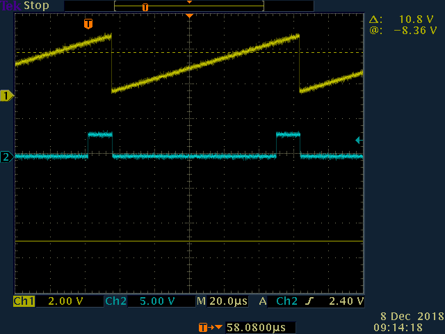
PinA mode test.
A test ramp is fed into PinA(#8). I then read the INx for the pin
and output the comparator state to anoher pin(#16). This works fine.
Here's the scope capture
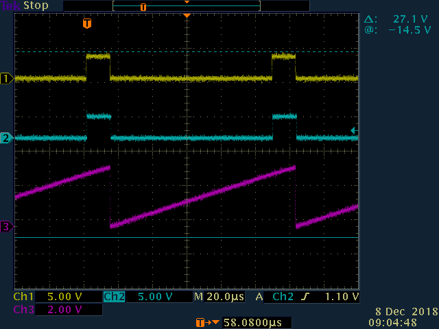
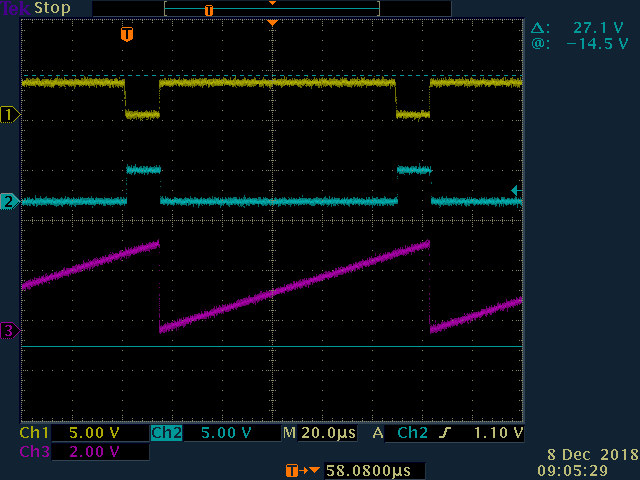
PinB mode test.
Further tests put the ramp into PinB(#9) with PinA(#8) set for output.
The comparator state is also read from INx and output to pin #16.
This also wotks fine for both %1110 and %1111 modes.
Here's the two scope captures.
My question is the Pad IO table shows options for PinA output while PinA is used
as the comparator input. This seems to be a invalid configuration.
Am I missing something here?
I've been testing the comparator modes in P2 and I have a question.
PinA mode test.
A test ramp is fed into PinA(#8). I then read the INx for the pin
and output the comparator state to anoher pin(#16). This works fine.
Here's the scope capture
PinB mode test.
Further tests put the ramp into PinB(#9) with PinA(#8) set for output.
The comparator state is also read from INx and output to pin #16.
This also wotks fine for both %1110 and %1111 modes.
Here's the two scope captures.
My question is the Pad IO table shows options for PinA output while PinA is used
as the comparator input. This seems to be a invalid configuration.
Am I missing something here?
Pad IO modes

M[12:0]		Input		PinA Output	CIOHHHLLL	OE	DAC	ADC	ADC mode	COMP
=============================================================================================================
1100_CDDDDDDDD	PinA > D	Out,1k5		C00001001	Dir	0	0	-		A>D
1101_CDDDDDDDD	PinA > D	!Input,1k5	C01001001	DIR	0	0	-		A>D
1110_CDDDDDDDD	PinB > D	Input,1k5	C00001001	DIR	0	0	-		B>D
1111_CDDDDDDDD	PinB > D	!Input,1k5	C01001001	DIR	0	0	-		B>D
=============================================================================================================
Here's my PinB test code
'%1111 mode (PinB > D, !Input)

dat		org

		wrpin	dacmode,#4		'ref out
		dirh	#4

		setbyte	compmode,#$df,#1	'threshold
		wrpin	compmode,#8
		dirh	#8

		rep	@loop,#0
		add	pa,#1
		setbyte	dacmode,pa,#1
		wrpin dacmode,#4		'set dac value
		testp	#8 wz
		drvz	#16			'comparator state
loop

dacmode		long	%0000_0000_000_10100_00000000_00_00000_0

compmode	long	%0000_0000_000_1111_000000000_00_00000_0
Comments
There is still a few question marks but I think I got most of the goodies in order.
The IN positive feedback mode %1110_CDDDDDDDD allows non-inverted feedback for using a transistor base or FET gate as the feedback delivery.
What is the speed of this mode ?
What is the common mode voltage range ?
A common spec point is to test 100mV overdrive tpd delays.
Vos is not going to be easy to measure - maybe drive to 0 & Vio, and feed a scaled variable supply to find vos.
Eg 1k & 10 ohms is 10mV/V
I think there is no/minimal hysteresis in this mode ?
It goes beyond the rails and has no intended hysteresis.