

Basic Stamp micro bot.
 AwesomeCronk
Posts: 1,055
AwesomeCronk
Posts: 1,055
Hello, I have a robot that I am making, small enough to fit in the palm of my hand.
I have run into an issue. My DC motors need at least 9v to operate, and I have no room to instal relays or drivers. I do not havee transisters at the time and do not have time to go get them. My Stamp is on a small 10x17 breadboard.
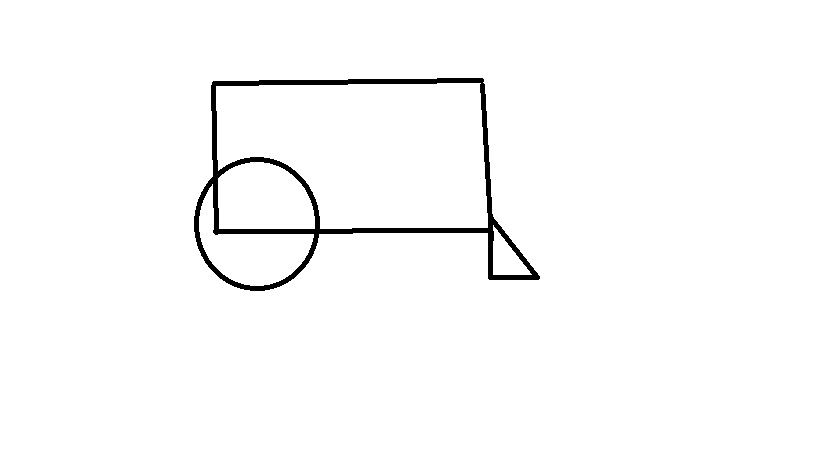
The triangle on the right of the image is a piece of cardboard to keep it off the ground.
How do I drive these motors?
I have run into an issue. My DC motors need at least 9v to operate, and I have no room to instal relays or drivers. I do not havee transisters at the time and do not have time to go get them. My Stamp is on a small 10x17 breadboard.
The triangle on the right of the image is a piece of cardboard to keep it off the ground.
How do I drive these motors?
Comments
You really need to know how much current the motors take and the minimum voltage for them to operate reliably. General purpose NPN switching transistors rated for the current and voltage needed are what you will need for drivers and Nuts and Volts Column #6 shows how to connect them. You also need a reverse connected flyback diode to prevent damage to the transistor and the Stamp from voltage spikes from the motor. The Nuts and Volts column shows that as well.
There are small DC motors that only need on the order of 3V. SparkFun has one of those. Given that the Stamp needs about 6V for Vin, a 6V motor might be best and a small one might draw 200mA.
The motor has a relatively low resistance. If you were to connect it between Vin and ground, it would probably conduct 100mA or more. By connecting it between Vin and I/O pin 0, it will "try" to conduct the same amount of current into pin 0. The little gold wires connecting the package pins to the chip pads can't carry that amount of current and will melt unless the connections on the chip itself melt first.
Also, the chip is not made to withstand voltages greater than about 5.5V and, before the program on the chip has a chance to initialize and set pin 0 to output mode low, pin 0 will be setup as an input (by default) that you've connected to Vin through the motor. This will place maybe 7.5V on pin 0 which will destroy some portions of the logic around pin 0 and possibly other portions of the chip as well.
Using servos is a good idea. The servos have built-in drivers and the control signal works with 5V (and usually 3.3V) logic parts. There are some pretty small servo motors available. Make sure you have what are called "continuous motion" servos that have been modified to move continually (through 360 degrees) with the control signal indicating the speed and direction of the motor. Regular servos use the control signal to indicate the position desired for the motor and the motor moves only through about 270 degrees.