

PPDB - Using the full PPDB - Updated Code Version 1.4

Updated to Version 1.4 December 3rd 2011
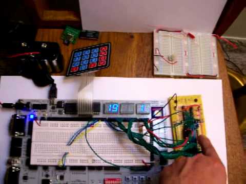
I am working on a project to fully use the PPDB with as little extra components as possible, so far I've had to add two PCA 9555 IC's and have added a 4x4 Matrix keypad that will be connected to one of the PCA9555 IC's. With the exception to the I2C Bus Expanders, I will be using parts available directly through the Parallax Store.
I will be updating this post as the project progresses. I anticipate the total cost of the project will be around $300 US for all the parts and the PPDB. I should also note that I will be adding a GPS Unit later, after I have a 4x4 Matrix Keypad working.
Parts Needed So Far:
Please see my Blog for more info http://forums.parallax.com/blog.php?53890-Jorge-P . In the mean time, here is a video. NOTE: This link will update as the project progresses.
Video will be updated Each time the code is updated.
Update Log:
V1.4
V1.3
Next Updates:
If there is still room, I will add some additional PCA9555's to access the dip-switch, Buttons, & LED's which will require at least 2 more.
I would like someone to help with reducing the spin code size, PM Me if you are willing.
I am working on a project to fully use the PPDB with as little extra components as possible, so far I've had to add two PCA 9555 IC's and have added a 4x4 Matrix keypad that will be connected to one of the PCA9555 IC's. With the exception to the I2C Bus Expanders, I will be using parts available directly through the Parallax Store.
I will be updating this post as the project progresses. I anticipate the total cost of the project will be around $300 US for all the parts and the PPDB. I should also note that I will be adding a GPS Unit later, after I have a 4x4 Matrix Keypad working.
Parts Needed So Far:
- PPDB
- Two PCA9555 IC's (Up to 7 can be added)
- Two 10k Ohm Resistors (For I2C) Brown, Black, Orange
- Wire
- 4x4 Matrix Keypad
Please see my Blog for more info http://forums.parallax.com/blog.php?53890-Jorge-P . In the mean time, here is a video. NOTE: This link will update as the project progresses.
Video will be updated Each time the code is updated.
Update Log:
V1.4
- Added the 4x4 Matrix Keypad on Propeller pins 8 through 15
- Pressing the * and # keys together on the keypad displays the date.
V1.3
- Changes to the code and pin outs.
- I can now display the date by pressing the PPDB's Button 0, and the date will display until you release the button.
- The previous version was 1.2 so this update is 1.3. (Code will be available by 5pm)
Next Updates:
- V1.5 - Update Time and Date with Keypad.
- V1.6 - Reattach the uM-FPU V3 to the I2C Bus and test.
- V1.7a - Attach GPS to the uM-FPU V3 and test.
- V1.7b - Compile uM-FPU code for GPS Great Circle math, setup commands to read just a date/time/GPS String/Latitude/Longitude/Speed/Course/Altitude all separately.
- V1.8 - Automatically update date and time according to GPS
- V2.0 - Attach an micro-SD card reader with 4GB card and test
- V2.?? - Micro-SD/OS related updates
- V3.0 - Attach TV Output and test.
- V3.?? - TV Related updates
If there is still room, I will add some additional PCA9555's to access the dip-switch, Buttons, & LED's which will require at least 2 more.
I would like someone to help with reducing the spin code size, PM Me if you are willing.
Comments
I missed what the second board wired to the PPDB was ( the little one toward bottom right).
Hope you get your flicker under control!!
The board in the lower right is one I made for the um-FPU V3 but I am not using it yet, the GPS unit, the red thingy in the video, will be connected to it on the I2C bus to update the time clock on startup. I will also be adding TV out if there is room in on the RAM but I can just add 1 or more 24LC256's at different addresses if I need more room and load them in another cog.
Aside from that... I am looking for code I saw a while ago but managed to lose it amongst all my files. I saw a method in a file that showed how to wait without pausing the cog, instead it just captured the current clock and resumed when it was a specific elapsed time from the capture. That's all I recall from it so I am lost at the moment as to what file/project I saw it in. I would like to use that section of code for reading the ds1302 in one second increments instead of multiple times a second like I am now.
I'll be digging into all this again in a few days...
http://forums.parallax.com/showthread.php?135882-DS1302-add-ons
I will try to remember to post all part numbers and sources with the next update in case anyone wants to rebuild this project.
I decided to start a separate side project for learning to read the 4x4 Matrix keypad with the PCA9555, after that I will try to read the keypad in this project. I am also having a problem with not being able to read interrupts from the PCA9555 bus extenders, Do I need a pull up/down resister on the interrupt line?
I will be using this project as a contest entry for the Quad Rover Contest. I will be placing all version archives on my website today or tomorrow, remind me if I get sidetracked, in case anyone wants to use it as a template for their own project. So far I've managed to keep the code to 626 longs, If BST is used it will be much less, 567.
As stated in the video above, I know it wont be useful to everyone, but it should be useful to some.
EDIT: I forgot to mention that this is all still using only 1 cog.
Did I fry a PCA9555? I know the one controlling to Digit is working, however the one controlling the segments seem to be the one with the issue... Can anyone with experience with the PCA9555 chips help out with this? I don't have any test equipment, but it looks like the data I am sending to the device is coming out reversed, On when it should be off, and off when it should be on. It's not a problem in code since I am testing it with the working code as in the video above.
One step forward, two steps back :frown:
I won't claim to have much experience with the chip in question, or even understand your issue correctly, but if the circuit is working with the bits reversed, just inverse them in your code as a work around. Eventually this thing will become impossible to move around without wires popping out and what not. Hard to say from the video, but unfortunately if you have a hardware issue here, you may need to bite the bullet, tear down that part of the circuit, and rewire it.
Your code is well organized and tidy. That has never been a priority to me, so I can really appreciate it and vouch for it's importance.
You can't dance without stepping backwards occasionally.
LED Driver for PPDB:
http://forums.parallax.com/showthread.php?129182-New-LED-driver-for-PPDB-Now-Available&highlight=ppdb+digits
I will have to wait until I can purchase more parts, and that may be a while, so I am going to just end the project here! I will never buy Radio Shack boards for a project again, the pads break and burn off too quickly even with a 25W iron.