

Minipter keyboard interface

This is a re-posting. The orginal post was accidentally deleted.
We have just completed the design and prototyping of a slightly complex keyboard interface system that we refer to as the Miniputer.
We will share the sample code (slightly unorganized) if you are familiar with multi-bank programs, but the schematics are proprietary since we hope this has a commercial future.
This system, when complete with all the optional peripherals, and with the sample program furnished, operates as follows:
When the system is powered on, the LCD display says "Enter command". It pauses for 5 seconds, displays the current time, pauses 5 seconds, then displays the output of Sensors 1 and 2. (In the prototype, these two sensor ports are connected LM34DZ temperature sensors, one reading outside, one reading inside). After another 5 seconds pause, it repeats the cycle continuously. A command may be entered anytime - it is stored in a buffer and is executed when the "Enter command" displays. There are two LEDs on the bottom edge of the PC board – the red LED, when on, indicates the system can accept a command. The green LED, when on, indicates that one or more relays are closed.
Pressing keys A, S or D closes Relays 1, 2 or 3. Relay contacts are ported to screw terminals on the top edge of the Slave PC. Contacts are lifeless and isolated - peripheral devices with their power supply can be operated from these terminals. Contacts are rated at 2amps@30VDC or [url=mailto:1amp@125VAC]1amp@125VAC[/url].
Each relay has a red LED that comes on when the relay is closed.
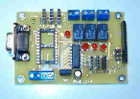
The Slave PC board is fitted with 3 DPDT relays and there are user options to add 4 more external relays. Contacts of the DPDT are connected in parallel to increase the current rating.
Pressing keys Q, W or E will open Relays 1, 2 or 3.
Pressing keys Z, X or C will display the readings for whatever sensor is connected to the respective sensor port, 1, 2 or 3. There are 3 additional sensor ports on the board but they are not included in the sample program.
All commands and readings are displayed on the LCD when they are executed, and remain displayed for 5 seconds. Vdd, Vss and serial data for the LCD are available at 3 screw terminals on the Master, and a 2-position screw terminal provides power for LCD backlighting, if used. The LCD uses the Combo backpack; if a standard serial LCD is used the necessary LCD commands would have to be added to the program since the Combo backpack uses only a SEROUT command to drive the LCD.
In addition to the above commands, pressing F will put the system in a "Calculator" mode. Once in this mode, the user may select Add, Subtract, Multiply or Divide by pressing the " + ", " -", " * " or " / " key.
In the Multiply and Divide modes, an integer may be multiplied or divided by a fraction; in the Divide mode answers are given to 2 decimal places.
Additionally, the user may extract the square root of any number up to 65535 by pressing the "\" key, or he may extract the cube root of any number up to 512 by pressing the G key. Square roots are displayed to 2 decimal places, cube roots to 3 decimal places.
The system has one more function – a timer. By pressing the M key, the BSE waits until the seconds of the current = 00, then it measures elapsed time until the M key is pressed again. This is not a true stopwatch – it measures time to the nearest second. I have found it very useful to determine how long it takes to accomplish a task, which simplifies calculating labor costs.
The Slave PC board has a 14-position header on the right edge which will accept a Parallax 433mHz transmitter. The bottom four holes of this header will accept a Rentron TWS transmitter. Three jumpers are provided to enable/disable the TWS transmitter. If using a Parallax transmitter, the jumpers must be removed.
The prototype uses the Parallax transmitter, and transmits the outside and inside frequencies to a remote receiver approximately every 15 seconds. The remote receiver can be programmed to receive and store data at whatever interval is desired.
For TWS users with a coax antenna, a ground pad for the coax shield has been placed near the antenna pads.
All sensor ports on the Slave have pads for a 1K stabilizing resistor for use with the LM34 and similar sensors. If a resistor is not needed the pads can be jumpered.
On the bottom edge of the Slave are 4 Master interface screw terminals for Ground, Vin, Serout and Serin. The Slave is powered by Vin from the master PC board but the user may supply 12VDC to the Vin terminal if he prefers. The board must have 12VDC to operate the relays. If a separate supply is used for the Slave then the Master will run from a 9VDC supply; otherwise the Master requires a 12VDC supply.
Both the Master and the Slave have DB9 connectors for programming. The Master can run from a BSE, BS2pe or a BS2p. The Slave requires at least a BS2, but will run from a BSE, BS2pe or a BS2p. For relay operation, the Slave has a ULN2003 - the 4 unused channels are ported to pads for user options.
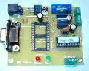
The Master has 4 small screw terminals on the bottom edge for connecting to the keyboard PS2 cable. Handling of the keyboard interface is accomplished by a PAK6A embedded in the Master PC board.
Separate 5VDC regulators are included for the keyboard and for the LCD.
Once both Stamps are programmed, this is a completely stand-alone system and may be operated in any location where a wall transformer can be plugged in. Alternatively, it could be operated from two lantern batteries connected in series. A 6 volt lantern battery has a capacity of 52,000 mah which would run the system for over a week, operating continuously.
I have attached 3 photos, one of the Master PC board, one of the Slave PC board and one showing the entire system. If you would like further info please contact me at Newzed@aol.com.
▔▔▔▔▔▔▔▔▔▔▔▔▔▔▔▔▔▔▔▔▔▔▔▔
Sid Weaver
Do you have a Stamp Tester?
http://hometown.aol.com/newzed/index.html
We have just completed the design and prototyping of a slightly complex keyboard interface system that we refer to as the Miniputer.
We will share the sample code (slightly unorganized) if you are familiar with multi-bank programs, but the schematics are proprietary since we hope this has a commercial future.
This system, when complete with all the optional peripherals, and with the sample program furnished, operates as follows:
When the system is powered on, the LCD display says "Enter command". It pauses for 5 seconds, displays the current time, pauses 5 seconds, then displays the output of Sensors 1 and 2. (In the prototype, these two sensor ports are connected LM34DZ temperature sensors, one reading outside, one reading inside). After another 5 seconds pause, it repeats the cycle continuously. A command may be entered anytime - it is stored in a buffer and is executed when the "Enter command" displays. There are two LEDs on the bottom edge of the PC board – the red LED, when on, indicates the system can accept a command. The green LED, when on, indicates that one or more relays are closed.
Pressing keys A, S or D closes Relays 1, 2 or 3. Relay contacts are ported to screw terminals on the top edge of the Slave PC. Contacts are lifeless and isolated - peripheral devices with their power supply can be operated from these terminals. Contacts are rated at 2amps@30VDC or [url=mailto:1amp@125VAC]1amp@125VAC[/url].
Each relay has a red LED that comes on when the relay is closed.
The Slave PC board is fitted with 3 DPDT relays and there are user options to add 4 more external relays. Contacts of the DPDT are connected in parallel to increase the current rating.
Pressing keys Q, W or E will open Relays 1, 2 or 3.
Pressing keys Z, X or C will display the readings for whatever sensor is connected to the respective sensor port, 1, 2 or 3. There are 3 additional sensor ports on the board but they are not included in the sample program.
All commands and readings are displayed on the LCD when they are executed, and remain displayed for 5 seconds. Vdd, Vss and serial data for the LCD are available at 3 screw terminals on the Master, and a 2-position screw terminal provides power for LCD backlighting, if used. The LCD uses the Combo backpack; if a standard serial LCD is used the necessary LCD commands would have to be added to the program since the Combo backpack uses only a SEROUT command to drive the LCD.
In addition to the above commands, pressing F will put the system in a "Calculator" mode. Once in this mode, the user may select Add, Subtract, Multiply or Divide by pressing the " + ", " -", " * " or " / " key.
In the Multiply and Divide modes, an integer may be multiplied or divided by a fraction; in the Divide mode answers are given to 2 decimal places.
Additionally, the user may extract the square root of any number up to 65535 by pressing the "\" key, or he may extract the cube root of any number up to 512 by pressing the G key. Square roots are displayed to 2 decimal places, cube roots to 3 decimal places.
The system has one more function – a timer. By pressing the M key, the BSE waits until the seconds of the current = 00, then it measures elapsed time until the M key is pressed again. This is not a true stopwatch – it measures time to the nearest second. I have found it very useful to determine how long it takes to accomplish a task, which simplifies calculating labor costs.
The Slave PC board has a 14-position header on the right edge which will accept a Parallax 433mHz transmitter. The bottom four holes of this header will accept a Rentron TWS transmitter. Three jumpers are provided to enable/disable the TWS transmitter. If using a Parallax transmitter, the jumpers must be removed.
The prototype uses the Parallax transmitter, and transmits the outside and inside frequencies to a remote receiver approximately every 15 seconds. The remote receiver can be programmed to receive and store data at whatever interval is desired.
For TWS users with a coax antenna, a ground pad for the coax shield has been placed near the antenna pads.
All sensor ports on the Slave have pads for a 1K stabilizing resistor for use with the LM34 and similar sensors. If a resistor is not needed the pads can be jumpered.
On the bottom edge of the Slave are 4 Master interface screw terminals for Ground, Vin, Serout and Serin. The Slave is powered by Vin from the master PC board but the user may supply 12VDC to the Vin terminal if he prefers. The board must have 12VDC to operate the relays. If a separate supply is used for the Slave then the Master will run from a 9VDC supply; otherwise the Master requires a 12VDC supply.
Both the Master and the Slave have DB9 connectors for programming. The Master can run from a BSE, BS2pe or a BS2p. The Slave requires at least a BS2, but will run from a BSE, BS2pe or a BS2p. For relay operation, the Slave has a ULN2003 - the 4 unused channels are ported to pads for user options.
The Master has 4 small screw terminals on the bottom edge for connecting to the keyboard PS2 cable. Handling of the keyboard interface is accomplished by a PAK6A embedded in the Master PC board.
Separate 5VDC regulators are included for the keyboard and for the LCD.
Once both Stamps are programmed, this is a completely stand-alone system and may be operated in any location where a wall transformer can be plugged in. Alternatively, it could be operated from two lantern batteries connected in series. A 6 volt lantern battery has a capacity of 52,000 mah which would run the system for over a week, operating continuously.
I have attached 3 photos, one of the Master PC board, one of the Slave PC board and one showing the entire system. If you would like further info please contact me at Newzed@aol.com.
▔▔▔▔▔▔▔▔▔▔▔▔▔▔▔▔▔▔▔▔▔▔▔▔
Sid Weaver
Do you have a Stamp Tester?
http://hometown.aol.com/newzed/index.html
300 x 239 - 7K
288 x 203 - 6K

450 x 385 - 16K
