

How to - Boe-Bot Line Following with 3 QTI Sensors
 Andy Lindsay (Parallax)
Posts: 1,919
Andy Lindsay (Parallax)
Posts: 1,919
Boe-Bot Line Following with 3·QTIs
Just one of the many Boe-Bot(R) robot QTI sensor applications is line following.· QTIs are relatively inexpensive and are great for line following because you can adjust their position, add or remove detectors, as well as use them in different ways depending on the course.·
·
The QTIs were originally developed for the SumoBot(R) robot, where they are used to detect the edge of the competition ring.· The SumoBot text demonstrates how QTI modules can be used as analog sensors with the RCTIME command.· By adding a resistor to the QTI circuit, you can make the sensor a purely digital device that returns a 1 when it detects a black line or a 0 if it detects a white background.·
·
This activity demonstrates how the QTIs can be used for digital line following on a simple 3/4-inch wide electrical tape course with a white background.
+ View full size

Parts List
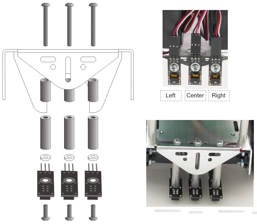
The picture above shows one of each of the parts you will need for this project.· Below is the parts list with quantities, Parallax part numbers, etc.
Parallax
Part Number···· Quantity··· Description
805-00001·· ··········· (3)········ 10-inch servo extension cable
800-00016·············· (1)········ 3-inch Jumper wires - bag of 10
150-01030·············· (3)········ Resistor - 10 k
555-27401·············· (3)········ QTI Sensor
451-00303·············· (3)········ MM Header - 3-pin
710-00007·············· (3)········ 7/8-inch screw, pan head,·4-40
700-00060·············· (3)········ Standoff, round, 1-inch, 4-40
713-00007·············· (3)········ Spacer, round, 1/2-inch
700-00002·············· (3)········ 3/8-inch screw, pan head,·4-40
700-00015·············· (3)········ Washer, nylon, fits screw size #4
Mounting the QTIs
The left side of the figure below shows how the QTIs are mounted on the Boe-Bot’s chassis with the screws, spacers and standoffs.·
+ View full size

Building the Sensing Circuits
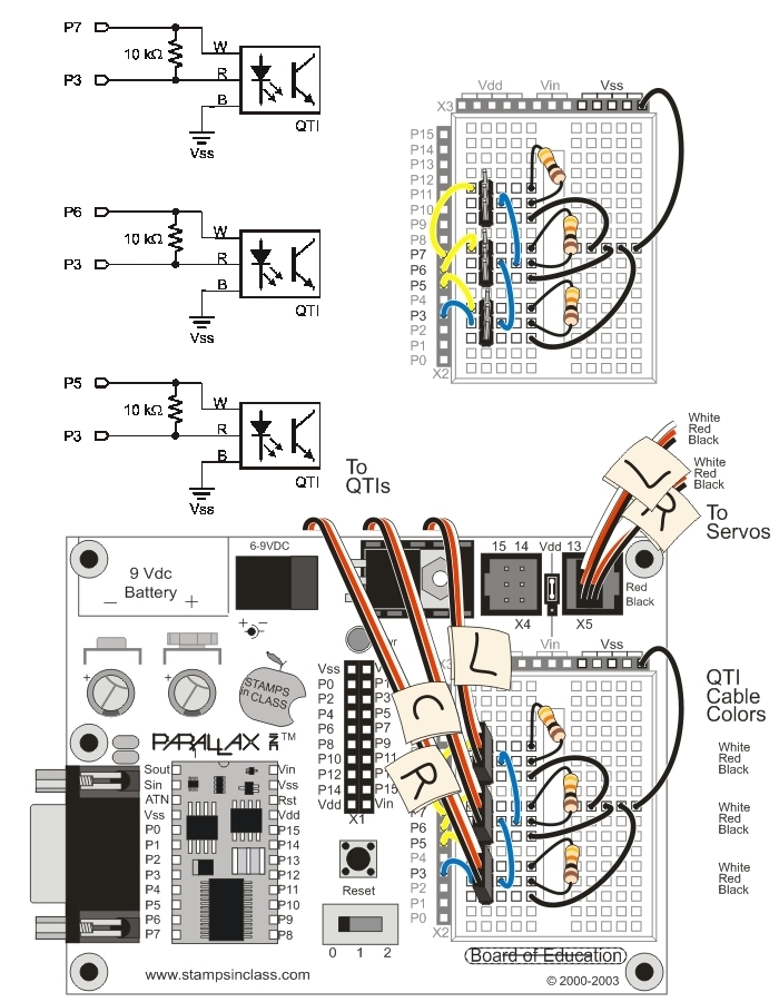
Each QTI can be converted to a digital sensor by adding a 10 k resistor across its W power input and its bidirectional R sense pin.··After applying 5 V to one of the QTI's W pins,·its R pin will be close to 5 V if it detects a black surface, and close to 0 V if it detects a white·surface.· In other words, it sends a binary-1 if it does not·see its IR reflection·or a·binary-0 if it does.·
·
Only one QTI should be turned on at any given time to make sure that a QTI doesn't see the reflection of another QTI's IR signal.· With this rule in mind, P5, P6, and P7 are each connected to one of the QTI's W pins.· P5 is connected to the right QTI's W pin, P6 to the center, and P7 to the left.··All the B pins are tied to Vss.· All the R pins are tied·together and connected to P3.· We'll only turn one QTI on at a time, then read P3.··If the QTI·that receives 5 V sees it's reflection, it will drive the voltage at P3 low; otherwise, it will be pulled high by the 10 k resistor.
+ View full size

How the Digital QTI Circuit Works
Although it's not exactly equivalent, at·Boe-Bot speeds the QTI circuit on the right is functionally equivalent to the actual QTI circuit on the left.· Looking at the circuit on the right, if black is connected to Vss, then the LED and transistor circuits can be turned on by applying 5 V (Vdd) to white, or turned off by disconnecting the voltage.· When the circuit is on, the IRLED emits infrared.· If the infrared is reflected by a surface near the QTI, it will cause the infrared transistor to conduct current.· When the transistor conducts current, it brings the red lead’s voltage close to 0 V (Vss).· If the QTI is close to electrical tape, which tends to absorb infrared, the transistor will detect very little reflected infrared.· It will in turn conduct less current, and the voltage at the red terminal will approach 5 V as it's pulled up by the 10 k resistor.·
+ View full size
·

Testing for Line Detection
It's a good idea to test all the sensors with the Debug Terminal before taking the Boe-Bot for a spin on the line following course.·
QtiBwDetect.bs2
How QtiBwDetect.bs2 Works
The program turns on power to the right QTI with the command HIGH 5.· Then, the command qtiLeft = IN3 stores the output sensed by IN3 in the qtiLeft bit variable.· INPUT 5 turns the right QTI off.· The process is repeated for the center QTI.· HIGH 6 turns on the center QTI.· qtiCenter = in3 stores the QTI's output, and INPUT6 turns the QTI off.· Keep in mind that a different I/O pin (P6) is used to turn the center QTI on, but the same I/O pin (P3) is used sense the QTI's output.· That's because each W (on/off) line is tied to an individual I/O pin (P5, P6, P7), but all the R (sense) wires are tied to P3.· The DEBUG command displays the binary QTI readings.· The leftmost digit indicates the state of the left QTI, the center digit indicates the center QTI, and the right digit indicates the right QTI.· PAUSE 100 is there to prevent serial buffer overload on slower computers.
Simple Line Following
QtiLineFollow.bs2 is designed to start following a line as soon as you place the center QTI over the electrical tape.· It will stop line following as soon as it runs out of electrical tape.· Start with an easy course, like a large S shape.·
·
QtiLineFollow.bs2
How QtiLineFollow.bs2 works
Instead of three bit variables, one nibble variable stores the three bit values.· One bit is unused, but it will come in handy for trying four QTIs.· The right QTI's output is stored in qti.BIT0, the center in qti.BIT1, and the left in qti.BIT2.· A SELECT...CASE statement examines the pattern of 1s and 0s in the qti variable, and then delivers servo pulses accordingly.· Only five of the eight possible cases are evaluated, one for each individual QTI, one for left + center, and one for right + center.·
Your Turn - Tuning, Challenges, Contests
Here are just a few ideas, things to try with your Boe-Bot and QTI line follower:
(c) 2004·by Parallax Inc - all rights reserved.··
Post Edited By Moderator (Jessica Uelmen (Parallax)) : 8/25/2010 6:22:12 PM GMT
Just one of the many Boe-Bot(R) robot QTI sensor applications is line following.· QTIs are relatively inexpensive and are great for line following because you can adjust their position, add or remove detectors, as well as use them in different ways depending on the course.·
·
The QTIs were originally developed for the SumoBot(R) robot, where they are used to detect the edge of the competition ring.· The SumoBot text demonstrates how QTI modules can be used as analog sensors with the RCTIME command.· By adding a resistor to the QTI circuit, you can make the sensor a purely digital device that returns a 1 when it detects a black line or a 0 if it detects a white background.·
·
This activity demonstrates how the QTIs can be used for digital line following on a simple 3/4-inch wide electrical tape course with a white background.
+ View full size
Parts List
The picture above shows one of each of the parts you will need for this project.· Below is the parts list with quantities, Parallax part numbers, etc.
Parallax
Part Number···· Quantity··· Description
805-00001·· ··········· (3)········ 10-inch servo extension cable
800-00016·············· (1)········ 3-inch Jumper wires - bag of 10
150-01030·············· (3)········ Resistor - 10 k
555-27401·············· (3)········ QTI Sensor
451-00303·············· (3)········ MM Header - 3-pin
710-00007·············· (3)········ 7/8-inch screw, pan head,·4-40
700-00060·············· (3)········ Standoff, round, 1-inch, 4-40
713-00007·············· (3)········ Spacer, round, 1/2-inch
700-00002·············· (3)········ 3/8-inch screw, pan head,·4-40
700-00015·············· (3)········ Washer, nylon, fits screw size #4
Mounting the QTIs
The left side of the figure below shows how the QTIs are mounted on the Boe-Bot’s chassis with the screws, spacers and standoffs.·
- Use the 7/8-inch screws to attach the 1/2-inch spacers and 1-inch standoffs to the underside of the chassis.·
- Use the 3/8-inch screw to·attach the QTI and nylon·washer to the other side of the standoffs.·
- Connect·each servo extension to a standoff.·
- Make sure the black wire lines up with the "B", the red wire lines up with the "R", and the white wire lines up with the "W" on the QTI.·
+ View full size
Building the Sensing Circuits
Each QTI can be converted to a digital sensor by adding a 10 k resistor across its W power input and its bidirectional R sense pin.··After applying 5 V to one of the QTI's W pins,·its R pin will be close to 5 V if it detects a black surface, and close to 0 V if it detects a white·surface.· In other words, it sends a binary-1 if it does not·see its IR reflection·or a·binary-0 if it does.·
·
Only one QTI should be turned on at any given time to make sure that a QTI doesn't see the reflection of another QTI's IR signal.· With this rule in mind, P5, P6, and P7 are each connected to one of the QTI's W pins.· P5 is connected to the right QTI's W pin, P6 to the center, and P7 to the left.··All the B pins are tied to Vss.· All the R pins are tied·together and connected to P3.· We'll only turn one QTI on at a time, then read P3.··If the QTI·that receives 5 V sees it's reflection, it will drive the voltage at P3 low; otherwise, it will be pulled high by the 10 k resistor.
- Click the circuit image below to view it at its original size.
- Insert the 3-pin headers into the breadboard·then, build the circuit.
- Plug the cables for the right, center and left QTIs into their corresponding 3-pin headers on the breadboard:
- Right·· -> P5
- Center -> P6
- Left···· -> P7
- Check to make sure you have your cables connected so that the black wire is connected to Vss, the red wires are bussed to P3, and each white wire·is connected to P5, P6, or P7.
+ View full size
How the Digital QTI Circuit Works
Although it's not exactly equivalent, at·Boe-Bot speeds the QTI circuit on the right is functionally equivalent to the actual QTI circuit on the left.· Looking at the circuit on the right, if black is connected to Vss, then the LED and transistor circuits can be turned on by applying 5 V (Vdd) to white, or turned off by disconnecting the voltage.· When the circuit is on, the IRLED emits infrared.· If the infrared is reflected by a surface near the QTI, it will cause the infrared transistor to conduct current.· When the transistor conducts current, it brings the red lead’s voltage close to 0 V (Vss).· If the QTI is close to electrical tape, which tends to absorb infrared, the transistor will detect very little reflected infrared.· It will in turn conduct less current, and the voltage at the red terminal will approach 5 V as it's pulled up by the 10 k resistor.·
+ View full size
·
Testing for Line Detection
It's a good idea to test all the sensors with the Debug Terminal before taking the Boe-Bot for a spin on the line following course.·
- Affix a few inches of 3/4-inch wide electrical tape to a white sheet of paper.
- Enter and run QtiBwDetect.bs2
- Place the left QTI directly over the electrical tape (and the other QTIs over white background).
- The Debug Terminal should read 100.
- Place the center QTI over the electrical tape; the Debug Terminal should display 010.
- Place the right QTI over the electrical tape: the Debug Terminal should display 001.
- Place the Boe-Bot so that the electrical tape between the·right and center QTIs; the Debug Terminal should display 011.
- Place the Boe-Bot so that the electrical tape between the·left and center QTIs; the Debug Terminal should display 110.
QtiBwDetect.bs2
' QtiBwDetect.bs2
' Boe-Bot detects electrical tape with 3 QTI modules.

'{$STAMP BS2}
'{$PBASIC 2.5}

qtiLeft        VAR     Bit
qtiCenter      VAR     Bit
qtiRight       VAR     Bit

DO

  HIGH 5: PAUSE 1: qtiRight   = IN3: INPUT 5
  HIGH 6: PAUSE 1: qtiCenter  = IN3: INPUT 6
  HIGH 7: PAUSE 1: qtiLeft    = IN3: INPUT 7

  DEBUG HOME, BIN1 qtiLeft, BIN1 qtiCenter, BIN1 qtiRight

  PAUSE 100

LOOP
How QtiBwDetect.bs2 Works
The program turns on power to the right QTI with the command HIGH 5.· Then, the command qtiLeft = IN3 stores the output sensed by IN3 in the qtiLeft bit variable.· INPUT 5 turns the right QTI off.· The process is repeated for the center QTI.· HIGH 6 turns on the center QTI.· qtiCenter = in3 stores the QTI's output, and INPUT6 turns the QTI off.· Keep in mind that a different I/O pin (P6) is used to turn the center QTI on, but the same I/O pin (P3) is used sense the QTI's output.· That's because each W (on/off) line is tied to an individual I/O pin (P5, P6, P7), but all the R (sense) wires are tied to P3.· The DEBUG command displays the binary QTI readings.· The leftmost digit indicates the state of the left QTI, the center digit indicates the center QTI, and the right digit indicates the right QTI.· PAUSE 100 is there to prevent serial buffer overload on slower computers.
Simple Line Following
QtiLineFollow.bs2 is designed to start following a line as soon as you place the center QTI over the electrical tape.· It will stop line following as soon as it runs out of electrical tape.· Start with an easy course, like a large S shape.·
- Enter and run QtiLineFollow.bs2.
- Place the Boe-Bot on the course so that the center QTI is over the electrical tape.
- If the QTIs passed the "Testing for Line Detection" tests, it should navigate the course with ease.··
- Try other courses to test the limits of the program.
- Try modifying the program to solve courses that the unmodified program could not solve.
·
QtiLineFollow.bs2
' QtiLineFollow.bs2
' Boe-Bot follows electrical tape with 3 QTI modules.

'{$STAMP BS2}
'{$PBASIC 2.5}

qti            VAR     Nib

DO

  Right:  HIGH 5: PAUSE 1: qti.BIT0 = IN3: INPUT 5
  Center: HIGH 6: PAUSE 1: qti.BIT1 = IN3: INPUT 6
  Left:   HIGH 7: PAUSE 1: qti.BIT2 = IN3: INPUT 7

  SELECT qti
    CASE %010          ' Forward
      PULSOUT 13, 850
      PULSOUT 12, 650
    CASE %011          ' Pivot right
      PULSOUT 13, 850
      PULSOUT 12, 750
    CASE %001          ' Rotate right
      PULSOUT 13, 850
      PULSOUT 12, 850
    CASE %110          ' Pivot Left
      PULSOUT 13, 750
      PULSOUT 12, 650
    CASE %100          ' Rotate Left
      PULSOUT 13, 650
      PULSOUT 12, 650
    ENDSELECT

LOOP
How QtiLineFollow.bs2 works
Instead of three bit variables, one nibble variable stores the three bit values.· One bit is unused, but it will come in handy for trying four QTIs.· The right QTI's output is stored in qti.BIT0, the center in qti.BIT1, and the left in qti.BIT2.· A SELECT...CASE statement examines the pattern of 1s and 0s in the qti variable, and then delivers servo pulses accordingly.· Only five of the eight possible cases are evaluated, one for each individual QTI, one for left + center, and one for right + center.·
Your Turn - Tuning, Challenges, Contests
Here are just a few ideas, things to try with your Boe-Bot and QTI line follower:
- Modify the program so that it smoothes out the Boe-Bot's responses to changes in the line's direction.· Your code should take steps toward a maximum speed each time it detects that a given pattern is detected.
- Detect intersections and make random turns.
- Add a fourth QTI and modify the SELECT...CASE so that the middle two QTIs follow the line, and the outer ones are only used for detecting sharper turns.·
- Try line following with just two QTIs.· How about one, can you do it?
- Challenge a friend, or set up a Boe-Bot line following competition.·
- Have fun!
(c) 2004·by Parallax Inc - all rights reserved.··
Post Edited By Moderator (Jessica Uelmen (Parallax)) : 8/25/2010 6:22:12 PM GMT

932 x 429 - 219K
898 x 782 - 104K
700 x 900 - 339K

848 x 246 - 31K
Comments
▔▔▔▔▔▔▔▔▔▔▔▔▔▔▔▔▔▔▔▔▔▔▔▔
Chris Savage
Knight Designs
324 West Main Street
P.O. Box 97
Montour Falls, NY 14865
(607) 535-6777
Business Page:·· http://www.knightdesigns.com
Personal Page:··· http://www.lightlink.com/dream/chris
Designs Page:··· http://www.lightlink.com/dream/designs
·
Also, a corrected and refined version of this post with some additional material is now available from the QTI Line Follower AppKit for the Boe-Bot page:
http://www.parallax.com/detail.asp?product_id=28108
See "QTI Line Follower AppKit Documentation (.pdf)" under Downloads.
Post Edited (Andy Lindsay) : 11/16/2004 5:58:23 AM GMT