

Is this hookup OK?
 Acadian
Posts: 16
Acadian
Posts: 16
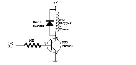
We are looking for a hookup for a stepper motor to our basic stamp 2.
This is what we found for a hookup. I tried to hook it up, but there is no activity on the stepper motor.
·
Can someone post a small sample of code that would make a stepper motor turn. I just want to make sure that it's the circuit and not the code. It's just a standard Nippon PF55-48C5 Unipolar Stepper.
·I forgot to mention that we are only allowed to hook it up with a 2n3904 and the Diode. No IC's for right now.
Any help would be greatly appreciated.
Thanks
Post Edited (Acadian) : 11/2/2004 3:05:39 AM GMT
461 x 223 - 20K
Comments
▔▔▔▔▔▔▔▔▔▔▔▔▔▔▔▔▔▔▔▔▔▔▔▔
Jon Williams
Applications Engineer, Parallax
Dallas Office
▔▔▔▔▔▔▔▔▔▔▔▔▔▔▔▔▔▔▔▔▔▔▔▔
Jon Williams
Applications Engineer, Parallax
Dallas Office
Your goal here *is* to saturate the transistor so that it acts like a 'switch'. Zero volts will 'turn-off' the transistor, 5 volts will turn it fully on. Thus you want a base-resistor that provides enough current into the transistor so it reaches that saturation state. A 470 ohm resistor should do that.
·This is my hookup.
If it makes any sense· The Yellow wire goes to the orange of the motor and the orange goes to the yellow.
Yea yea I know why not use the same color? My code in my bs2 is just. Although it doesn't look like it, the left diode is connected to the collector to +5v and it's parrallel with the Orange which goes to +5V common rail on top.
START:
HIGH 3
HIGH 4
PAUSE 100
LOW 3
LOW 4
GOTO START
Post Edited (Acadian) : 11/4/2004 12:37:25 AM GMT
Here is an example of one of the reason's I'm asking. If you are using Vdd for +V on the BASIC Stamp HomeWork Board, you are probably drawing too much current from the BASIC Stamp's voltage regulator. Use Vin for +V (assuming that your power supply/battery is not outside the coil's voltage rating).
I tried plugging an external power source like a 5V adapter and before I turn the stamp on the LED is dimly lit.
I didn't want to chance turning on the stamp.
I just disconnected the power rail at the top and the ground at the bottom and plugged the +5V of the adapter to top and the Ground to the bottom.
We removed the motor connection to test what we are getting on the pin output and it's always +5V there is no switching at the emitter.
If we put the meter on the Base it switches from +5V to 0V.. So our transister is not switching on and off
Post Edited (Acadian) : 11/4/2004 12:48:31 AM GMT
At this point, I would pull the stepper motor out, and make sure I can control light emitting diodes with the transistors first.
I would then perform manual switching (without the BASIC Stamp) to make sure I can control the stepper with the transistors by moving the wires from Vdd to Vss and back.
After that, try putting the two together. Remember to disconnect power whenever you change the circuit.
The Board of Education has two power supplies, Vin, which is the battery supply, and Vdd, which is the regulated 5 V supply for the BASIC Stamp. Vin could be 6 V, 7.5 V, 9 V, etc. It depends on what you've connected to the battery clip/power jack. The negative terminal of the battery is connected to Vss. If you're using a 9 V battery, this means Vin is 9 V when you use Vss as a reference. If you use a voltmeter to measure across the 9 V battery's + and - terminals, it will read something in the neighborhood of 9 V. Plug the battery into the Board of Education's battery clip, and put the voltmeter across Vin - Vss, and you will also see 9 V. Of course, this assumes you will connect the negative lead of your voltmeter to Vss (the 9 V battery's negative terminal).
Vdd is regulated to + 5 V regardless of the voltage at Vin. The 3-pin voltage regulator just above the Board of Education Rev C's LED power indicator has three terminals. One for Vin, one for Vss, and a third for its 5 V regulated output. This is a second power supply, with its negative terminal connected to Vss.
Let's say you needed negative nine volts (- 9 V) to power an opamp. (Don't try this now, you've got enough trouble shooting on your plate. Remember it though.). You could connect the positive terminal of a second 9 V battery to Vss. That second battery's negative terminal would be - 9 V compared to Vss. I posted a thread a little ways back that details this called "How to - Piezospeaker Volume Control".
I got my transistors to switch on and off. I want to use an adapter to power the motor's Common and to provide the +V for the Phases... The only thing I want the Stamp to do is send a signal to the Base of the transistor.. Turning it on and off.
I would like to know if I can connect my Adapter's Ground together with the Stamps VSS on a seperate Breadboard. I just don't want to damage anything on the Basic Stamp.
Your picture above shows that you have already connected the ground of the Board of Education to the Stepper Motor Circuit ground. I see a black wire going from Vss to the rail that is connected to the transistor emitters.
I also see Vin going to the stepper motor. One potential problem is that Vdd is connected to the diode anodes. In your schematic at the beginning of this thread, it shows the diode cathodes connected to the same power supply as the coil. This means that the diode cathode terminal should be connected to the same supply as the motor coils. Right now, it looks like you have the coils connected to Vin and the diodes connected to Vdd.
Your text in the·picture is also claiming that Vss is +5 and Vdd is ground. That's not correct either. Vdd is + 5 V and Vss is ground.·
What's the voltage and coil resistance ratings for your stepper motor? This will dictate whether you want to connect both diode cathodes and coil inputs to Vin or Vdd.
Post Edited (Andy Lindsay) : 11/5/2004 4:47:02 AM GMT
Your picture above shows that you have already connected the ground of the Board of Education to the Stepper Motor Circuit ground. I see a black wire going from Vss to the rail that is connected to the transistor emitters.
I also see Vin going to the stepper motor. One potential problem is that Vdd is connected to the diode cathodes. In your schematic at the beginning of this thread, it shows the diode cathodes connected to the same power supply as the coil. This means that the diode cathode terminal should be connected to the same supply as the motor coils. Right now, it looks like you have the coils connected to Vin and the diodes connected to Vdd.
Your text in the picture is also claiming that Vss is +5 and Vdd is ground. That's not correct either. Vdd is + 5 V and Vss is ground. However, it does look like you have correctly connected Vss to the emitters of the 2N3904s, so that's fine.
What's the voltage and coil resistance ratings for your stepper motor? This will dictate whether you want to connect both diode cathodes and coil inputs to Vin or Vdd.
If you want to use two completely separate supplies, there should be a common ground.· If one of the supplies is a wall wart, it will be safest if the other is a battery.· The negative terminal of the battery can be connected to the wall wart's negative terminal.· Two separate batteries can also have their negative terminals connected (separate positive terminals).··Connecting the grounds of two separate wall warts can cause problems.· Although it works most of the time, there are sometimes hidden gotchas that can cause serious problems.
Your transistors are rated for 200 mA continuous current max.· You might want to use Ohms law to calculate how much current each coil is going to draw.· That's +V divided by coil resistance.· If the value is above 0.2, you will be over taxing the transistor.· Since your instructor wants you to drive the coils with transistors, you might need to connect two or more transistors in parallel to handle the load.