

Display driver architecture
 MagIO2
Posts: 2,243
MagIO2
Posts: 2,243
This is actually a spinoff of the following thread: https://forums.parallax.com/discussion/172972/waveshare-1-5-oled-grayscale-display
But it turned out that the piece of code I wrote is more general and refering to a waveshare display is not feasible anymore (even if all 3 display drivers currently included are waveshare, but more to come ;o)
I just created a pull request in the Object Exchange.
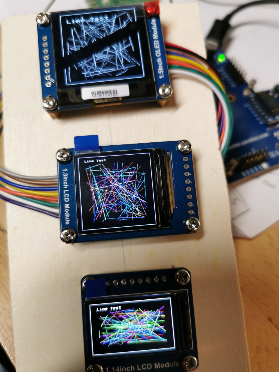
In my test setup, I run all 3 in parallel, driven by one COG on the fly ... meaning there is no dedicated display driver COG "wasted". It just runs in the SPIN2 code COG.
!ATTENTION! ... there is one file, which did not make it into the ZIP, because it is not referenced by the demo. It is a template to create hardware drivers for other displays. Here is a reference to the Object Exchange version:
https://github.com/MagIO2/propeller/blob/master/libraries/community/p2/All/GraphicsDisplayDriverArch/Brand_b_x_LCDDrv.spin2

Comments
Copied from the other thread, but updated whenever there is something new. Last update 17.04. @ 00:20 CEST.
Latest changes: https://github.com/MagIO2/propeller/tree/master/libraries/community/p2/All/GraphicsDisplayDriverArch
Now the code is in a state clean enough to post it here ... and in the object exchange as well!
At least it shows the following:
Current functionality of driver:
Current functionality of graphics:
Known limitations (fixit list ):
):
Next todo's:
Somewhen in future:
Congratulations!
Nice work.
Have you measured the power requirements for each of these displays?
I found that the 1.44" 128x128 color SPI (often miss-named 5110 color) could be powered from P1 or P2 pins. This made plugging in to P1 and P2 boards easier.
Thank you!! That looks great (and a lot of work too).
I have not bought any other LCD since Nokia 5110! Bought one later to found by myself their horror histories about bad QA and reliability.
Please let us know about those different models (and their quality!).
Look out FTDI / Bridgetek.....Prop2 is gonna eat your lunch")
Added a link to a template for hardware drivers to the first post. Hope it makes your life easier in case you want to use this architecture for your own displays. The more drivers we have, the easier it is to kickstart projects with displays.
@Cluso99 : will work on your question in the evening. Quick response: All 3 displays are driven by the 3.3V connections of the Eval Board ports. But now that you're asking ... maybe the 240x240 display looks not as bright as the 240x135 because it is operating at the edge of power supply capacity. Will check that.
@both: Thank you for the flowers. Still a lot of work ... much more functionality planned ... guess there is a lot potential to improve code as well. But remember, this is my first project for P2. Still have to dig through all the PASM2 instructions. ;o) But it is functional and might already help.
@Cluso99 :
Here are the results
All in all the test setup was drawing below 300mA on the USB-Port.
@Ramon :
I've linked the product pages in the respective hardware drivers. So you can find specs and demo code there.
The OLED display has it's weaknesses. I don't have long term experiences with it, but when reading about OLED displays, I've heard that they tend to get worse over time. If you can't compare it with something else, it is OK.
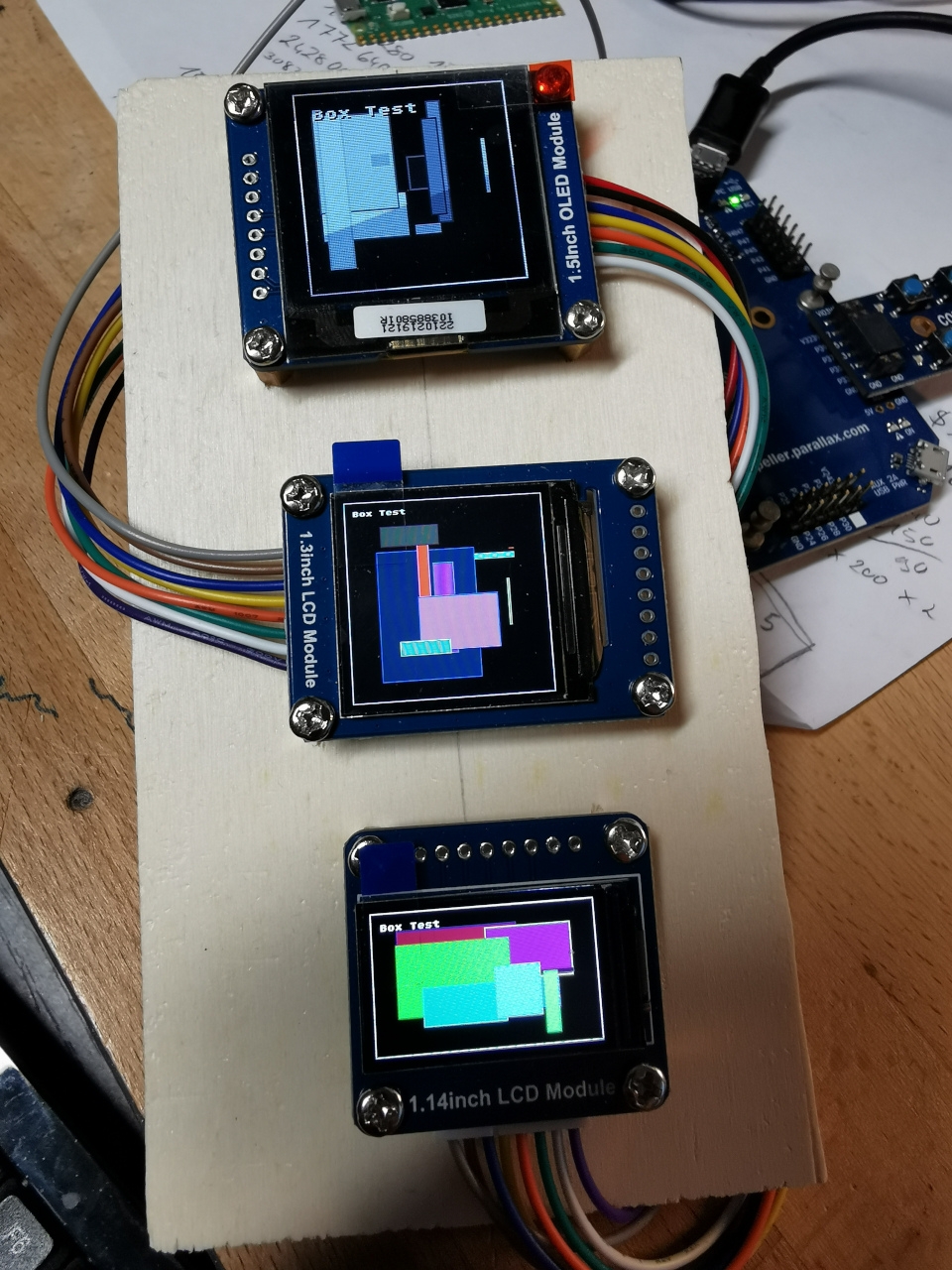
In the test code it shows problems in the box-test. I just print 100 random boxes with random border and infill colors. So, depending on the contrast in the display line, you can see some ghosting, where after a dark area, the brighter area behind gets brighter than the lines above or below with the same grayscale value.
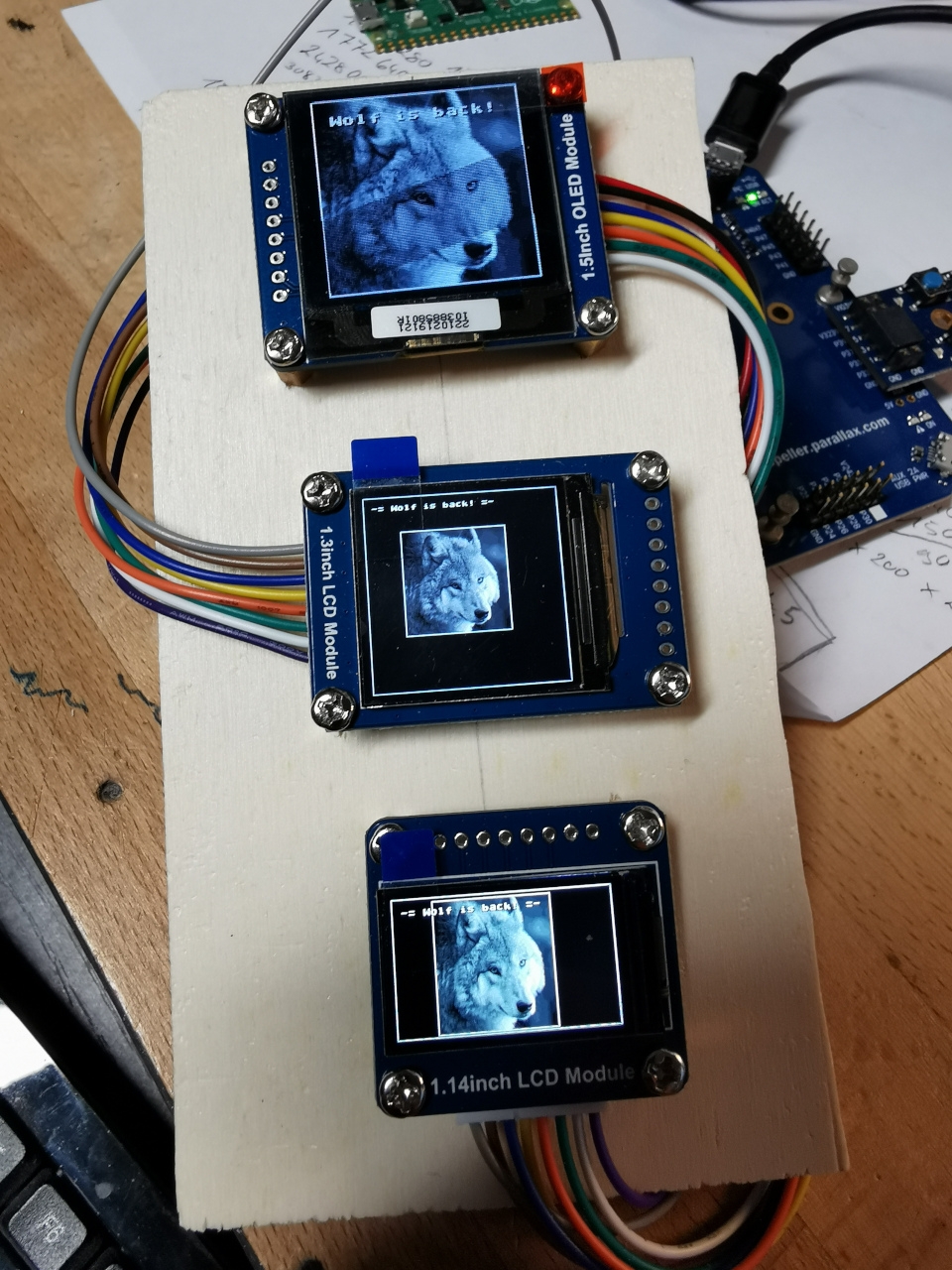
Line test and image test are quite good, so it likes chaos and darkness better then having dark details on a brighter background.
Positive is the independence of the viewing angle.
The 240x240 has the highest dependence of the viewing angle and is somewhat darker than the smaller 240x135 display. I'd also say, that the grayscale it produces has a small tendency to a warmer white. Not sure if that can be changed by tweaking some parameters in the setup. I simply use the defaults and attached the brightness control to fixed 3.3V. If you can't compare it, is is good.
The 240x135 is somewhat brighter and shows a nice image from every angle. Best one in this round.
@cgracey & all
Fun!
Just created a driver which uses DEBUG. So the debug driver has the same settings, as one of my physical displays. I let the real display driver create the screen-buffer and additionally send it to the debug window.
Of course serial is a bit slow. Even more so, because the UHEX_WORD_ARRAY_ does not behave as expected. I think it would make sense to add a
RAW_WORD_ARRAY_(@buffer, len) which would allow so send raw data. Then the transfers would not add extra bytes for each line.
   debug(`bitmap DispEmu title 'DisplayEmulation' SIZE 240 240 RGB16 TRACE 0 RATE 57600 SCROLL 0 0)
   repeat i from 0 to bytes/2-1
     debug(`DispEmu `uhex_(word[adr][i]))

   'debug(`DispEmu `UHEX_WORD_ARRAY_( adr, 57600 ))
PS: On my windows box, when I click "Minimize" of the debug output window, the window dissappears. But I don't know how to get it back except stopping Propeller Tool and restart it. Is there a trick I should know?
New version uploaded to github and to the first post.
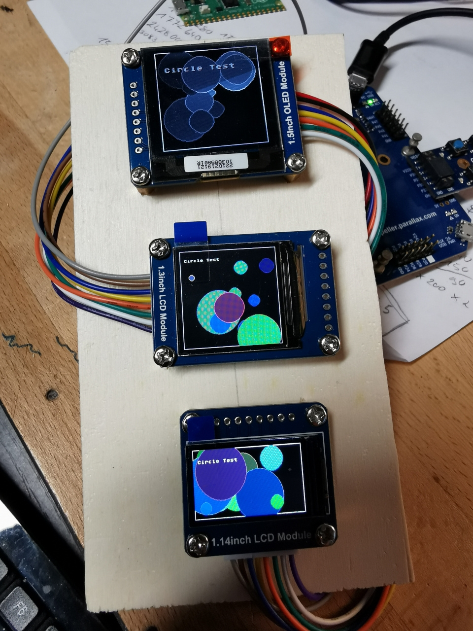
Now the circle function has been converted to PASM2 and a function which can draw an 24RGB bitmap file to the color screens has been added.
Together with the clipping function, it also supports partial writes of rectangular area (into the screen buffer).
Everything ready to write nice GUIs, I would say.
Thanks.
Unfortunately these all draw way too much current to be powered by a P2 pin.
A GUI would be a nice driver")
I just measured my 1.3" 240x240 (ST7789) and I saw 13.5mA on Vcc at 3V3. Background is white.
Cluso, Do you have two models? 1.44" and 1.3" that can be powered by a single P2?
Please can you post picture (or link) of your LCDs? I want to check If I can find them here. Thank you.
The 1.44” 128x128 can be powered by the P2. The 1.3” 240x240 is a bit high but ok at 13.6mA but MagIO2 version takes double this (it’s not quite the same as it’s an 8pin version).
There are pics and links in the 4.0” 480x320 and the RamBlade2 (now you have one) threads. You’ll need to search for these as I’m on my iPad without link info. Also see the Quick Byte post too.
If you cannot locate the threads, post here and when I’m on my pc I’ll post links.
Just here to report or tease? ;o) Latest version in Github has now the MIT license added. But all the goodies here are not yet in. Code has to go through QA first.
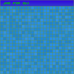
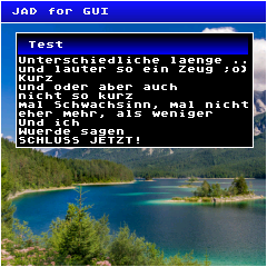
Above you see some objects which are not yet cleaned up to be released and more going on at the moment. The desktop object only creates some background or uses an image.
The text window is writing a text-buffer to a window, making use of the clipping rectangle, the text-buffer can be bigger than number of characters that fit into the window. When adding a line to the buffer it is auto-scrolling. Some nice helper functions for scrolling are still needed.
The part which is using hardware RAM windows of the displays is done and even works together with the debug bitmap window, so the bitmap window can be updated partially.
What you see above is a quick test for the P2P2 Cube. It contains some code which wraps the drawings around 6 screens. What you see in those bitmap savings created by debug are the 6 screens of a virtual cube, one lonely screen top left, 4 screens in the middle row and another single screen in 3rd row and the circle is scrolling across. The tricky part will be the wraparound on the y axis. Will see how it works out. The code is ready in a way that it knows which screen to use when -y or +y wraparound happens, but I need to figure out how to "mirror" or "swap" the coordinates.
As I don't have the hardware for a P2P2, I simply created an emulated cube in the debug window within my GraphicsDriverArchitecture.
A lot more to do ... to make the text wrap around correctly, the text function needs to be able to rotate the output. Will see where this ends.
Exciting stuff MagIO2! Took me a moment to make sense of how you're projecting that onto the cube.
Which of those squares is top? the upper left one?
Hi Tubular.
Yes, the upper left one would be the top and the lower left the bottom display.
I decided to move the P2P2 Cube part to the P2P2Cube thread. There you can find my current version of the code. Now it wraps around circles which are drawn in one of the circumference screens (center is in one of those 4 screens). Top and bottom handling still needs to be implemented. The code is running in a debug window, no hardware needed.
https://forums.parallax.com/discussion/172696/p2-p2-cube#latest