

PCB tester (was: looking for small LCD graphics display)
 ManAtWork
Posts: 2,076
ManAtWork
Posts: 2,076
I'd like to use the P2 for production test of my PCBs. I think it's quite ideal for that task because it has many pins, can easily generate all sorts of signals and can not only compare digital output signals against test patterns but can also verify the voltage levels against upper/lower limits because every pin also has an ADC. You could even measure resistance, impedance and cross talk between traces with the goertzel mode...
The simplest possible tester would have a zero force socket for the device under test, a pushbutton to start the test and a green and a red LED to display success or failure. But that's a bit too simple. At least a text display to show error messages or diagnosis data would be helpful.
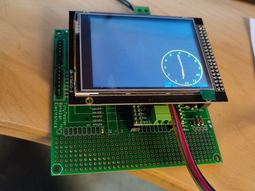
My new 3D printer has a small color graphics LC display which even has touch screen functionality. It's a bit overkill for a tester but I think those gadgets are pretty cheap theese days and if somebody has already written a driver for one of them it would be cool.
I don't care about a few $ more or less. I'm more worried about long term availability. So it should be a display type that is widely used so that we can get spare parts if something breaks.
Comments
I use a 4.0" SPI like this one on eBay
https://ebay.com/itm/4-0-inch-TFT-LCD-Touch-Screen-Display-Module-Board-480-x-320-Pixel-SPI-Interface/303764085840?hash=item46b9c01c50:g:Na4AAOSwkYpfrdwo
There are two LCD threads where I have written code to display blocks, lines circles, a clock face, etc, and the new one with small 8x8 text. There are pics on the thread and I've just released new common drivers for the text. Sorry, haven't implemented color switching in my new text driver as yet. My graphics includes color and has text to - it's a more specific driver.
Maybe I bought mine on AliExpress - yes
https://www.aliexpress.com/item/4001122632293.html?spm=a2g0o.store_home.productList_270037084.subject_1
It was the 4.0in with ST7796S chip and touch - careful some say touch but they don't have the IC so they are not really touch. Note currently none in stock. Not sure about the ILxxx chip - I programmed a 1.44" LCD that had an ILxxx chip and used that code for this one with a few mods.
Newhaven is a reliable source, they stock stuff for years... There are others, just look on Digikey and Mouser. If they appear on both, probably OK.
This is the first thread, I guess: https://forums.parallax.com/discussion/172370/4-0in-tft-spi-480x320-lcd-st7796-driver-and-tcs2046-touchscreen-support/p1
Where is the second?
Looks amazing but I think 40x60 characters text display is way too much for my application. I think the 1.44" would fit better. I wonder why the chinese dealers on ebay and Ali express all don't provide a data sheet. Do theese displays all use the same driver IC so that any model would work (except the parallel versions, of course)?
I almost always use one of the P2 - VGA drivers for all my test and product work projects, easy peasy, cheap and simple.
Yes, that’s one thread.
The other is titled starting with “Standalone fotmatter object....” It’s the LCD part. Started yesterday.
There is both a P1 and a P2 thread for those 1.44” colour LCDs. The driver I did for those has basic drawing and text methods, again with the clock face. The beauty of thes is 5hey can be powered directly from P1 or P2 pins (providing power and ground from normal prop pins")
They are about$4 on fleabay. Often referred to as Nokia 5110 color although AFAIK they have nothing to do with Nokia 5110. They use an ILxxx driver chip.
IIRC there is a link from my RetroBlade2 thread - the one that says you have your RetroBlade2 so what can you do with it. If you get the wrong RetroBlade2 thread, there’s a link in th3 first post to the other thread. Sorry I’m on my iPad so searching and posting links isn’t easy.
Here are a few links
https://forums.parallax.com/discussion/172370/4-0in-tft-spi-480x320-lcd-st7796-driver-and-tcs2046-touchscreen-support#latest
1.44in code ILI9163
https://forums.parallax.com/discussion/comment/1509348/#Comment_1509348
It took a while but now everything fits together... I'm just routing the layout for some sort of "motherboard" for the KISS module.

It has:
Planned applications:
I need 5!
Looks nice @ManAtWork . I guess you have the screen but would having the option of some LED indicators also be useful if you have some free pins and space left? Maybe LEDs makes sense only if you don't fit the screen. They could show the output state or for debug etc.
@rogloh I think I will always put the LCD on so I don't need LEDs to display the test result. In the case some application should require some they can be fitted onto the patch space.
But a pushbutton makes sense, sometimes. The touch panel gives no tactile feedback and it wears out or doesn't react very well on oily or dirty fingers. A good-old pushbutton survives much longer. Some of our test equipment was used to test 5000+ units.
@ErNa Ok, I'll order 10, 5 for me and 5 for you. But I don't know if it makes sense to pre-assemble all of them. The resistor dividers on the inputs need to be fitted to the application and there are lots of them. Maybe I only assemble the absolutely required sub-circuits (voltage regulator) and leave the rest empty.
Every production test system I've seen has been PC-based. I agree that the P2 would be an amazing i/o controller for such a test system, but UI would generally be done on Linux with a backing database recording detailed test results, potentially with serial numbers. That way, if any particular failure becomes more common than another, you can consider design changes to reduce its likelihood in later revisions.
Plus, if you do want to print serial number stickers for each device, you could keep track of failures in the field and correlate them with test measurements that may have been a pass, but should maybe be considered a failure.
I totally agree if the device to test is a full CNC controller or anything that needs a test report. But we manufacture a lot of small modules, cables and adaptors. We test the modules before we assemble everything together. This way we can fix shorts, for example, before we apply full power and there is no risk of damaging the main board.
If you only test a small sub-system there is no need for a test report. A short message "short on pin 5 detected" is enough. And if the tester is portable any employee can take it to his workbench as he needs it. A full blown and dedicated test bench with PC, printer etc. is expensive and takes much to much space. And if there is a problem then the whole production comes to halt. I rather prefer the de-centralized way. Many small and inexpensive testers are better. If there is a problem you can take a backup from the shelf.
Today, I assembled some of the tester boards. They work but I have kind of messed up the 3rd dimension. I thought mounting the KISS board on low-profile headers and the display on standard headers would work. But it doesn't. I have to add some extra spacers.

That does look nice, and I agree about smaller/accessory boards.
I've been thinking about tester architecture lately, and realized that Prolog would be a good language for specifying pass/fail criteria. I wonder if there's a prolog-specific vm that would be easy-ish to port to the prop2.
A bit off topic, but what did you use for the Kiss board power connector?
Jim
There are two version of the KISS board. The first one (I used in the picture) has a socketed screw terminal for power, the second has a mini USB connector. Bot none of them are required here because the KISS board gets its power from the main board over the 5V pins of the pin headers. Theres a wide input range voltage converter 10..60V to 5V on the main board.
I bet you used a battle proven solution for that s10..60V to 5V switching regulator. What was the chip you used, if you don't mind the question ?
The LM5007 is really good for industrial applications. It can be powered from 24 or 48V DC which is used in some stepper or servo drives. I fear the maximum current of 0.5A might be not enough for some applications. The P2 seems to be far more power hungry than the P1where 100mA was enough even with all cogs runing at 80MHz.
The 0.5A at 24V DC is plenty for the P2 - that's 3A at 4V DC and twice as much at 48V input but yes, some additional hardware might swallow some of that juice too. For this tester it looks like an excellent match though.
No, not 0.5V input at 24V but 0.5A max. output at 5V.
I've just found out that two cogs idling almost all the time already draw 0.2A. Well, the KISS board has a switching regulator for 1.8V so that's below 0.1A at 5V.
I hope that the testing applications don't require much memory bandwidth. The LCD should require much less power than an HDMI video output.
That changes things considerably but just for the testing algorithms it still should be fine. The LCD should not draw all that much current but it remains to be seen what the final verdict will be.
Same as every year: Christmas is coming soon and totally unexpected . So there is not much time to do anything (re-) creational. But at least I have finished my first tester board.


The device under test is hot-plugable, of course, and all inputs and outputs from/to the P2 are protected. The tester waits for a button to be pressed before the supply voltage is applied. Then the outputs of the voltage regulators are measured and all IOs are tested with a shifting bit pattern.
If any of the test steps fails the corresponding result is printed in red so that problems can easily be identified.