

Using the P2 Edge with breadboards
 Dave Hein
Posts: 6,347
Dave Hein
Posts: 6,347
I do most of my tinkering with solderless breadboards. I wanted to use the P2 Edge and the accessory boards with a breadboard, so I developed a couple of adapters to make it work. The P2DIP44 brings out 38 I/O pins to two 22-pin headers with 0.1" pin spacing. The two headers are spaced 0.6" apart. GND, RESn, P64 and P63 are grouped together so that a Prop Plug can directly interface with it. Four of the 3.3V outputs that correspond to four groups of eight I/O pins are also brought out to the headers.
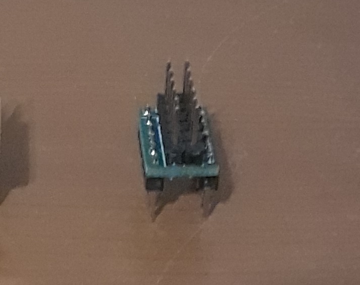
The other board is the AccAdapt that is used to adapt the 0.1" spacing of the accessory board connector to a 0.3" spacing so that it can plug into a breadboard. This is a simple PCB that consists of 4 rows of 6 pins each with the first row connected to the second, and the third row connected to the fourth. I've tried it out with the AV accessory board, and it works great.
I have quite a few extra boards if anyone is interested in getting some. It cost about the same to make 30 boards as it did to make one. Send me a PM if you want some.

1060 x 697 - 164K
713 x 565 - 74K

1216 x 705 - 259K

1367 x 1099 - 357K

1310 x 1625 - 433K

1032 x 700 - 356K
Comments
Thanks, Ken Gracey
The right angle adapter PCB needs to be completely reworked (not yet available as far as I can tell) The biggest issue is that the R/A connector pins spacing is completely different from the standard straight thru-hole connector.
Nice to have besides an actual PCB adapter, would be a layout template (a Macro) that anyone can drop in place when they are designing their own custom PCB board. Working on it...
I'm not sure that a right angle PCB adapter is practical. It takes up a lot of space. I did a layout, and the PCB is 34mm by 58mm. With the P2 Edge plugged in its around 58mm by 58mm. A dual DIL version of the P2 Edge would be better.
EDIT: If an adapter PCB isn't used the footprint of the connector plus the P2 Edge is about 58mm by 50mm. The clearance below the P2 Edge is about 3mm, so it's possible to place low-profile components on the PCB below the P2 Edge. If the components are taller than 3mm then an adapter board is needed to provide more clearance.
Although the .lib DipTrace file that Parallax posted apparently needs to be opened in a newer version than I am using (I'm still on ver. 2.4), the .pdf that they posted does show a 0.1" (2.54 mm) row spacing for the straight connector. And your post confirmed it for me. Actually, I've ordered both kinds of connectors from Parallax (along with the P2 Edge), but my order is apparently stuck at the airport/Customs in my country (for 10 days now, likely due to a holiday backlog and/or Covid-19). Anyway, I'm glad that I didn't send my board out for mfg. Thanks again for clarifying the difference between the two connectors.