

P2 Edges does Pan and Tilt with Gimbal
 iseries
Posts: 1,452
iseries
Posts: 1,452
in Propeller 2
A recent discussion about analog input got me thinking about trying it out. The problem is that most of the examples are done in SPIN and I only to C.
I had done a pan and tilt with a gimbal before with the P1 and that worked out rather well with the use of an MC3202 Analog to Digital converter. The MC3202 is a 12-bit unit that was needed as the gimbal unit even though uses 5k pots has limited movement. The total change in resistance is only 600 ohms full range or 300 ohms in each direction. That doesn't leave a lot of room.
So the first task was to build a function to enable a pin for analog mode and then read the values returned.
So this code will return the raw 14-bit value recorded on the pin. In this case, a low value was about 7317, and a high value of about 9985.
The other direction was 6742 and 9525. The values moved around by about +/- 5 units which is good.
After getting the gimbal working I needed to drive two servos, pan and tilt. After reading some documentation and looking at the object exchange
again I settled on the Sawtooth pin configuration. The name to me suggests that the pin outputs a sawtooth which does not match PWM.
So I set up the example code and hooked up my prop scope and looked at the results. At first, I got nothing because I didn't understand how the PWM pins worked on the breadboard. They are labeled 1 through 8. So does that mean pins 1 through 8. well it turns out you have to run a jumper from a pin to one of the input pins labeled 1 through 8. In addition there is a resister in between the input pin and the output pin.
Good thing I used a scope to see what was happening and quickly figured out where my signal was. And it look just like a PWM pulse, great.
Here is the code for the PWM function:
have a range of 400 to 2400. So I wrote two scaling functions to convert my input values to my output values.
Here is the final program:
Here is a video of the servos in action.
P2 Pan and Tilt
Mike
I had done a pan and tilt with a gimbal before with the P1 and that worked out rather well with the use of an MC3202 Analog to Digital converter. The MC3202 is a 12-bit unit that was needed as the gimbal unit even though uses 5k pots has limited movement. The total change in resistance is only 600 ohms full range or 300 ohms in each direction. That doesn't leave a lot of room.
So the first task was to build a function to enable a pin for analog mode and then read the values returned.
#include <propeller.h>
 #include "Analog.h"

 void SetAnalog(int pin)
 {
     int vss;
     int vdd;

     __asm volatile {
         fltl	pin							// reset smart pin
         wrpin	##(P_ADC | P_ADC_GIO), pin  // read ground reference
         wxpin	#13, pin					// 8192 samples
         wypin	#0, pin						//
         dirh	pin							// enable pin
         waitx	##(8192 << 2)				// allow 4x readings
         rdpin	vss, pin					// save ground cal level

         fltl	pin							// reset smart pin
         wrpin	##(P_ADC | P_ADC_VIO), pin 	// read 3.3v reference
         wxpin	#13, pin					// 8192 samples
         wypin	#0, pin						//
         dirh	pin							// enable pin
         waitx	##(8192 << 2)				// allow 4x readings
         rdpin	vdd, pin					// save Vio (3.3v) cal level

         fltl	pin							// reset smart pin
         wrpin	##(P_ADC | P_ADC_1X), pin  	// read input, no scaling
         wxpin	#13, pin					// 8192 samples
         wypin	#0, pin						//
         dirh	pin							// enable pin
         }
 }

 int AnalogValue(int pin)
 {
    int v;

     __asm volatile {
         rdpin v, pin
     }
    return v;
 }
This code came from a SPIN sample in the object exchange. Some of the code is not needed but I left it in there.So this code will return the raw 14-bit value recorded on the pin. In this case, a low value was about 7317, and a high value of about 9985.
The other direction was 6742 and 9525. The values moved around by about +/- 5 units which is good.
After getting the gimbal working I needed to drive two servos, pan and tilt. After reading some documentation and looking at the object exchange
again I settled on the Sawtooth pin configuration. The name to me suggests that the pin outputs a sawtooth which does not match PWM.
So I set up the example code and hooked up my prop scope and looked at the results. At first, I got nothing because I didn't understand how the PWM pins worked on the breadboard. They are labeled 1 through 8. So does that mean pins 1 through 8. well it turns out you have to run a jumper from a pin to one of the input pins labeled 1 through 8. In addition there is a resister in between the input pin and the output pin.
Good thing I used a scope to see what was happening and quickly figured out where my signal was. And it look just like a PWM pulse, great.
Here is the code for the PWM function:
#include <propeller.h>
#include "Digital.h"


void EnablePWM(int pin)
{
    int freq;
    int position;

    freq = _clkfreq / 1000000;
    freq |= 20000 << 16;
    position = 1500;

    __asm volatile {
	   fltl	pin									// set pin off
	   wrpin	##(P_OE | P_PWM_SAWTOOTH), pin	// set sawtooth mode
	   wxpin	freq, pin						// set 20msec
	   dirh	pin									// start pin
	   wypin	position, pin						// set motor position
	}
}

void SetPWM(int pin, int value)
{
    _wypin(pin, value);
}
Now I just needed to put all the pieces together. I also needed to scale my input values so that they worked with my servos. The servoshave a range of 400 to 2400. So I wrote two scaling functions to convert my input values to my output values.
Here is the final program:
 #include <stdio.h>
 #include <stdlib.h>
 #include <propeller.h>
 #include "Analog.h"
 #include "Digital.h"

 int scalet(int);
 int scalep(int);

 #define VERTICAL 31
 #define HORIZONTAL 32
 #define SERVO1 4
 #define SERVO2 5

 int pan[16];
 int tilt[16];


 void main()
 {
     int i;
     int p, t;
     int ps, ts;
     int pp, pt;
     int x;

     SetAnalog(VERTICAL);
     SetAnalog(HORIZONTAL);
     EnablePWM(SERVO1);
     EnablePWM(SERVO2);

     p = 0;
     t = 0;
     for (i=0;i<16;i++)
     {
         pan[i] = AnalogValue(HORIZONTAL);
         p += pan[i];
         tilt[i] = AnalogValue(VERTICAL);
         t += tilt[i];
     }

     i = 0;
     while (1)
     {
         t -= tilt[i];
         tilt[i] = AnalogValue(VERTICAL);
         t += tilt[i];

         p -= pan[i];
         pan[i] = AnalogValue(HORIZONTAL);
         p += pan[i];

         i++;
         i = i & 0x0f;

         ps = scalep(p/16);
         ts = scalet(t/16);

         if (pp != ps)
         	x = 1;
         if (pt != ts)
         	x = 1;

         if (x)
         {
//             printf("Pan: %d, Tilt %d\n", ps, ts);
             pp = ps;
             pt = ts;
             x = 0;
         }

         SetPWM(SERVO1, ps);
         SetPWM(SERVO2, ts);

     	_waitms(1);
  	 }

 }

int scalep(int v)
{
    int i;

    i = 2000*(v-7325)/(9994-7325)+400;

    return i;
}

int scalet(int v)
{
    int i;

    i = 2000*(v-6745)/(9527-6745)+400;

    return i;
}
Here is a video of the servos in action.
P2 Pan and Tilt
Mike

1280 x 720 - 187K
Comments
It is what the P2 Edge is all about. I can see possibly thousands of applications for stuff like this. Either manual or automated instrumentation, numeric/analog controls, robotics, who knows what - and really not all that hard compared to what is in the market right now.
It's been a few years since I did this setup and I see now that it needs some updating.
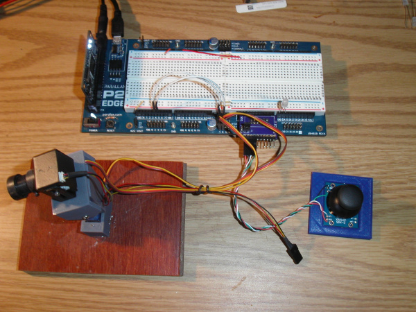
First off Parallax doesn't sell those gimbals any more just the small joysticks which works just as well. I removed the pins from mine and soldered some wires on so I could make it plug and play for my setup.
The is also simpler since Flex Prop has some of the functions built in.
#include <stdio.h>
 #include <stdlib.h>
 #include <propeller.h>
 #include <smartpins.h>

 int scalet(int);
 int scalep(int);


 #define VERTICAL 17
 #define HORIZONTAL 16
 #define SERVO1 4
 #define SERVO2 5

 int pan[16];
 int tilt[16];


 void main()
 {
     int i;
     int p, t;
     int ps, ts;
     int pp, pt;
     int x;

     // start read vertical position - 10 bits
     _pinstart(VERTICAL, P_ADC | P_ADC_1X, 9, 0);

     // start read horizontal position - 10 bits
     _pinstart(HORIZONTAL, P_ADC | P_ADC_1X, 9, 0);

     // start servo one at center position
     _pinstart(SERVO1, P_OE | P_PWM_SAWTOOTH, _clkfreq / 1000000 | (20000 << 16), 1500);

     // start servo two at center position
     _pinstart(SERVO2, P_OE | P_PWM_SAWTOOTH, _clkfreq / 1000000 | (20000 << 16), 1500);


     p = 0;
     t = 0;
     for (i=0;i<16;i++)
     {
         pan[i] = _rdpin(HORIZONTAL);
         p += pan[i];
         tilt[i] = _rdpin(VERTICAL);
         t += tilt[i];
     }

     i = 0;
     while (1)
     {
         t -= tilt[i];
         tilt[i] = _rdpin(VERTICAL);
         t += tilt[i];

         p -= pan[i];
         pan[i] = _rdpin(HORIZONTAL);
         p += pan[i];

         i++;
         i = i & 0x0f;

         // scale value to 1000 - 2000
         ps = 1000 * (p - 2784) / (13479 - 2784) + 1000;

         // scale value to 1000 - 2000
         ts = 1000 * (t - 2880) / (13760 - 2880) + 1000;

         if ((pp >> 2) != (ps >> 2))
            x = 1;
         if ((pt >> 2) != (ts >> 2))
            x = 1;

         if (x)
         {
             printf("Pan: %d, Tilt %d\n", ps, ts);
             pp = ps;
             pt = ts;
             x = 0;
         }

         _wypin(SERVO1, ps);
         _wypin(SERVO2, ts);

        _waitms(1);
     }

 }
The smart pin startup code makes it a one liner as well as the servo code. The scaling code had to be changed as the resistor sizes are different than the gimbal was.
Servos move nice and smooth with no jerking around.
These small MT900 servos work just fine from the supplied 5v power.
Now if only the P2 could read NTSC data and process the picture coming from the camera.
Mike
I think someone did have an NTSC reading code here somewhere, but was monochrome, as I recall...
https://forums.parallax.com/discussion/comment/1500491/#Comment_1500491
I think color decoding is doable but it might take several cogs for the full frame rate.
I wish we could have a 2GHz P2 with faster analog converters.
It's just $1M away. Maybe $2M with inflation.
More people would be interested in a smaller packaged part first. I now think BGA is an option given the thermal pad requires oven soldering anyway.
there is some code for cameras with 8-bit data bus in the forum here... NTSC does have some definite pin count advantages though...
@cgracey MIPI input would be the way to go for P3. Also, HDMI input would be nice and almost the same thing...
Yes! We just need a smaller process. Nothing that maybe $1.5M couldn't achieve. We have to make more money on P2 first.
I've seen silicon valley ventures burn through hundreds of millions of dollars and produce sometimes nothing. We could do more for a lot less.