

Repurposing laptop screen for P2 VGA - success
 Cluso99
Posts: 18,069
Cluso99
Posts: 18,069
Two weeks ago I decided to breakdown the parts from two non-working laptops, an HP/Compaq Presario CQ61 and a Lenovo 8918A18. The screens from these were both 15" and working.
From the Compaq, I recovered the screen, an Optronics B156XW02 Rev2 1366x768 with internal voltage driver.
From the Lenovo, I recovered the screen, a Samsung LTN154X3-L02 1280x800 with external voltage driver.
The Compaq housing was nicer ie thinner and easily modified to remove the hinges, etc. Plus it had an internal voltage driver so a simpler controller could be used.
I ordered an NEW HDMI+DVI+VGA LCD Controller Kit for B156XW02/LTN156AT02 LED Panel 1366x768 from fleabay for US$16.65 shipped. It arrived last Friday.
So I have modified the housing with a slot to connect the new controller cable from the back of the housing to the pcbs.
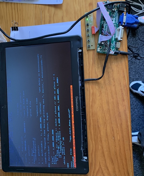
Today I tried the controller. It works with my P2 and Chip's VGA demos
BTW while the screen works with the controller board, the menu is in Chinese? and currently I'm not sure how to change it to English.
https://ebay.com/itm/NEW-HDMI-DVI-VGA-LCD-Controller-Kit-for-B156XW02-LTN156AT02-LED-Panel-1366x768/163654619792?ssPageName=STRK%3AMEBIDX%3AIT&_trksid=p2057872.m2749.l2649
Next: To make a 3D printed box to house the boards on the back of the monitor, and also make a mounting bracket to stand up the monitor.
Of course, it would have been cheaper/easier to scrounge an old VGA monitor, but there's no fun in that!
From the Compaq, I recovered the screen, an Optronics B156XW02 Rev2 1366x768 with internal voltage driver.
From the Lenovo, I recovered the screen, a Samsung LTN154X3-L02 1280x800 with external voltage driver.
The Compaq housing was nicer ie thinner and easily modified to remove the hinges, etc. Plus it had an internal voltage driver so a simpler controller could be used.
I ordered an NEW HDMI+DVI+VGA LCD Controller Kit for B156XW02/LTN156AT02 LED Panel 1366x768 from fleabay for US$16.65 shipped. It arrived last Friday.
So I have modified the housing with a slot to connect the new controller cable from the back of the housing to the pcbs.
Today I tried the controller. It works with my P2 and Chip's VGA demos
BTW while the screen works with the controller board, the menu is in Chinese? and currently I'm not sure how to change it to English.
https://ebay.com/itm/NEW-HDMI-DVI-VGA-LCD-Controller-Kit-for-B156XW02-LTN156AT02-LED-Panel-1366x768/163654619792?ssPageName=STRK%3AMEBIDX%3AIT&_trksid=p2057872.m2749.l2649
Next: To make a 3D printed box to house the boards on the back of the monitor, and also make a mounting bracket to stand up the monitor.
Of course, it would have been cheaper/easier to scrounge an old VGA monitor, but there's no fun in that!

577 x 705 - 170K
Comments
Then I designed and 3D printed a box base to mount the controller board to the back of the screen section. I goofed with the placement of the pcb mounting pads so I dremeled them off and printed just the mounting pads and glued them in the correct place. You cannot see inside the box so it was easier than a reprint of 2 3/4 hrs. Next I glued the box base onto the rear of the screen.
I have the box top printing now
Then I will need to design a stand.
BTW I have left room in the box to mount the configuration pushbuttons and LED but this is not necessary as the monitor works without them connected anyway. I may design a new switch pcb, or cut down the supplied pcb, so I can mount it on the edge as it takes up less space this way.
And the completed box on the back of the screen
And with the VGA and power cables connected
And finally for good measure, I printed my new avatar
Nice job, looks excellent!
Takes me ages to work my way around Fusion 360. It’s a total dogs breakfast. Nothing seems intuitive, not even the basics. I have to search YouTube’s for everything I try.
I have a parametric box design that I use as a base - just change the parameters (access like a spreadsheet and change dimensions) and you can export to an .stl file. Open the file in Prusa’s Cura and a couple of clicks and you have a gcode file for printing.
I use the free Fusion 360 which puts your designs on their website. It’s mangled software - if you want to export more than one object to print (a top and bottom box, or 4 mounting pads) it must use their website and it takes simply ages to create the stl. Do a single object and it’s seconds.
I have a Creality Ender 3 printer. Cheap ~$200. Just watch the YouTube videos to set it up properly. It comes partially assembled but you need to tweak the assembly to get good prints. I did this and I get great prints. My son has one too. We both bought the glass bed extra when I bought mine. First print was amazing.
We moved recently. My first print started lifting on one corner - needed the bed levelling - easy as once you know how - a minute and all good!
A good intro for Fusion 360 is Paul McKorter??? YouTube “using fusion 360 or die trying”. I can post the parametric box file or any of these prints if anyone wants them. Just ask.
Are you using it as an input from a P2 board?
Would have been cheaper/quicker to just scrounge an old VGA monitor, but where's the fun in that
I made two copies of my stand after I tried a single version and decided I needed to make it a little bigger and needed two of them. They are folding stands glued to the back of the screen, with hinges top and bottom achieved with M2x20 screws (threaded bolts).
This is the Fusion360 model
And the finished product
Of course I could not spend all my time on this without Mrs Cluso wanting her piece of the action... So I made her an iPad mount to attach to the handlebars on her exercise bike. 3D printers are great
My LCD monitor is 1366x768 which gives 160x64 characters using an 8x12 font.
So I've been testing with Chips VGA_1280x1024_text_160x85.spin2 program. After checking I realised that there is some rescaling going on in the VGA board or the LCD itself. I am still getting the 85 lines of text with 12 lines per char from the 8x12 font. So 85*12=1080 but the LCD is only 768 lines. I am not quite sure how the scaling is working. I played around with the font to see what's happening but I'm at a bit of a loss.
I think the pixel lines are being interpolated - I put alternating bits all-on and all-off in the lines of one of the characters ("0") and there isn't a really definitive bar of pixel lines present as I would expect. BTW the text is totally readable.
Anyone have any ideas?
It's very likely that it supports scaling arbitrary resolutions - if you were using it on a PC, not having that would be a disaster, as you wouldn't be able to see, say, 720x400 text mode screens (although you rarely get them these days...). You should get 1:1 pixel mapping when feeding the native panel resolution though.