

Request for input - The P2D2 as a Raspberry Pi "Hat"
 Stephen Moraco
Posts: 303
Stephen Moraco
Posts: 303
Ideas, feature conceptualization
As you likely already know Peter Jakacki's P2D2 Boards are arriving with a 3rd header, matching the Raspberry Pi GPIO pinout, outboard of the two P2D2 headers already present. This allows the P2D2 to be plugged into the Raspberry Pi just like many other RPi Hats.
I'm writing this post to hopefully start a broad discussion of the many forms of application/experimentation opportunities we can begin to visualize for this pairing.
I do have an early request for readers and contributors to this thread. I have one question to ask, but first, let's look at how these two devices are connected.
The Hardware
The RPi is an internet-connected machine while the P2 (as Jeff M. says) can be thought of as an I/O expander for the RPi, but with the added advantages that the P2 brings in accurate signal generation and measurement.
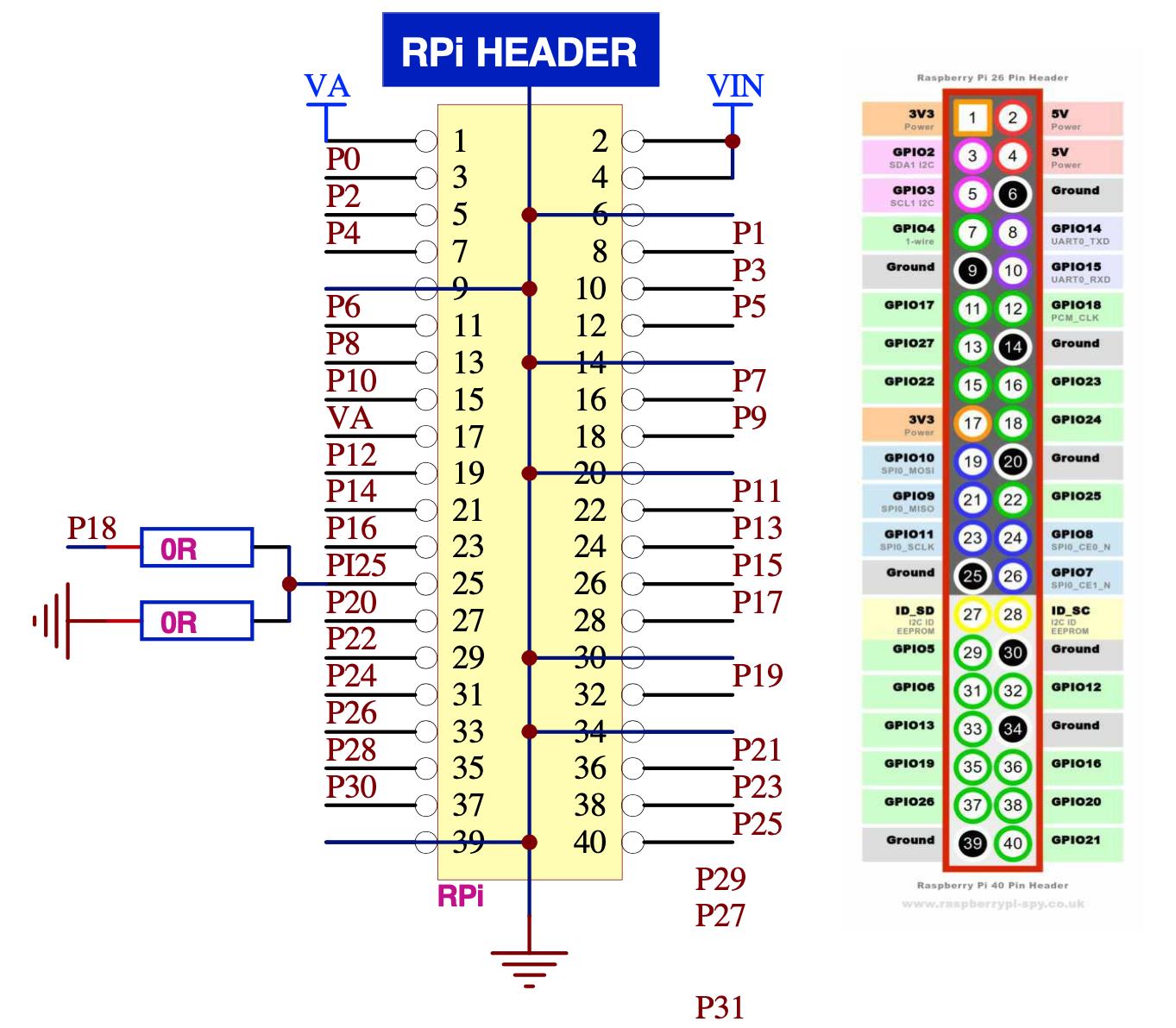
Pins that are connected to the RPi
By plugging the P2D2 onto the RPi header the board is immediately connected to a number of useful interfaces and a new world of opportunity.
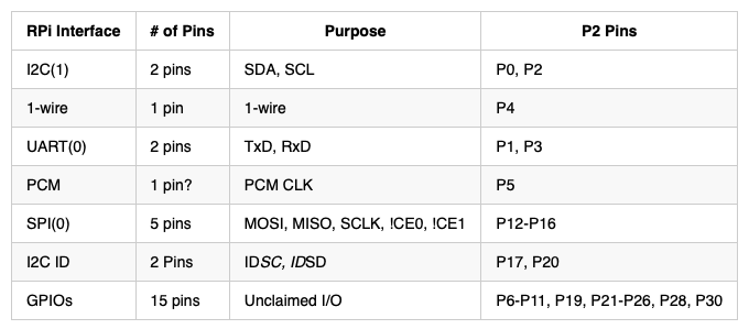
Diagram of connections to RPi
Here is the header as shown in Peter's P2D2 r5 documents:
The Raspberry Pi (RPi)
Raspberry Pi's are fairly inexpensive devices and all software for them, operating system, applications are free. RPi's such at the RPi4 with its 8GB ram is a reasonable linux machine. It is well connected, offering WiFi, wired ethernet, and bluetooth interfaces, USB 2.0 and 3.0. It has wonderfully high resolution (up to 4k 60fps) HDMI output and it has quite reasonable open source data analysis and visualization tools available at no cost (open source.)
Starting to see the Possibilities
Raspberry Pi I/O is generally thought of as slower, certainly not realtime, etc. However through the use of a fairly simple-to-write Loadable Kernel Module (LKM) we can improve the responsiveness to the I/O, add significant buffering opportunities, even dedicate one of the four cores if we wanted, to the interface(s) we choose to use between the RPi and the P2. The LKM could expose elements of the P2 world via the /proc tree on the RPI and/or could expose custom object-like interfaces (high level commands or chains of commands) between the kernel and applications running on the RPi.
Why my interest
I happen to have done a bit of Raspberry Pi work (scripting, playing with stuff, experimenting with the GPIO performance I can achieve using traditional OS and simple loadable kernel extensions.) I have way too many of these RPi's... but I'm not an advocate, I'm just a slightly more experienced user in some ways. I'm eager to blend what I've learned with my RPi work with work on my long time favorite processor, especially since we're playing with the P2!
Pre-discussion Discussion
Ok, now back to my one early question:
With all of your P1 and now early P2 experience, what would you say is the minimum viable set of capabilities that we would need to enable the broadest use and exploration with this new hardware pairing? And what would your priorities be for the order of implementation of these capabilites?
(I'm asking this so that we can jump start the development based on your answers.)
To start our thinking... maybe we need things like:
Ok one last something just to wet the whistle of your "minds eye" ;-)
-Metaphor mix-master me
Imagine the debugger you've been seeing Chip demo but now the debugger is running on the RPi displaying its output on the large attached 4K HDMI screen - displaying data live from the attached P2 with each of the cores displaying to their own debug windows. Just like Chip's you simply download and run anew and all the windows repaint based on the new debug.
This is just a brainstorm... just an example to get us thinking out loud in this thread.
Thanks for reading this! I look forward to this discussion.
-Stephen, KZ0Q
As you likely already know Peter Jakacki's P2D2 Boards are arriving with a 3rd header, matching the Raspberry Pi GPIO pinout, outboard of the two P2D2 headers already present. This allows the P2D2 to be plugged into the Raspberry Pi just like many other RPi Hats.
I'm writing this post to hopefully start a broad discussion of the many forms of application/experimentation opportunities we can begin to visualize for this pairing.
I do have an early request for readers and contributors to this thread. I have one question to ask, but first, let's look at how these two devices are connected.
The Hardware
The RPi is an internet-connected machine while the P2 (as Jeff M. says) can be thought of as an I/O expander for the RPi, but with the added advantages that the P2 brings in accurate signal generation and measurement.
Pins that are connected to the RPi
By plugging the P2D2 onto the RPi header the board is immediately connected to a number of useful interfaces and a new world of opportunity.
Diagram of connections to RPi
Here is the header as shown in Peter's P2D2 r5 documents:
The Raspberry Pi (RPi)
Raspberry Pi's are fairly inexpensive devices and all software for them, operating system, applications are free. RPi's such at the RPi4 with its 8GB ram is a reasonable linux machine. It is well connected, offering WiFi, wired ethernet, and bluetooth interfaces, USB 2.0 and 3.0. It has wonderfully high resolution (up to 4k 60fps) HDMI output and it has quite reasonable open source data analysis and visualization tools available at no cost (open source.)
Starting to see the Possibilities
Raspberry Pi I/O is generally thought of as slower, certainly not realtime, etc. However through the use of a fairly simple-to-write Loadable Kernel Module (LKM) we can improve the responsiveness to the I/O, add significant buffering opportunities, even dedicate one of the four cores if we wanted, to the interface(s) we choose to use between the RPi and the P2. The LKM could expose elements of the P2 world via the /proc tree on the RPI and/or could expose custom object-like interfaces (high level commands or chains of commands) between the kernel and applications running on the RPi.
Why my interest
I happen to have done a bit of Raspberry Pi work (scripting, playing with stuff, experimenting with the GPIO performance I can achieve using traditional OS and simple loadable kernel extensions.) I have way too many of these RPi's... but I'm not an advocate, I'm just a slightly more experienced user in some ways. I'm eager to blend what I've learned with my RPi work with work on my long time favorite processor, especially since we're playing with the P2!
Pre-discussion Discussion
Ok, now back to my one early question:
With all of your P1 and now early P2 experience, what would you say is the minimum viable set of capabilities that we would need to enable the broadest use and exploration with this new hardware pairing? And what would your priorities be for the order of implementation of these capabilites?
(I'm asking this so that we can jump start the development based on your answers.)
To start our thinking... maybe we need things like:
- Harness the UART pins as a serial debugger output to the RPi / input from the RPi
- Full debugger display tool (re-code of Chip's debug tool) running on the RPi
- Add Debugger write to file and read from file sending to P2 as input
- ... i'm sure you have better ideas than I ...
Ok one last something just to wet the whistle of your "minds eye" ;-)
-Metaphor mix-master me
Imagine the debugger you've been seeing Chip demo but now the debugger is running on the RPi displaying its output on the large attached 4K HDMI screen - displaying data live from the attached P2 with each of the cores displaying to their own debug windows. Just like Chip's you simply download and run anew and all the windows repaint based on the new debug.
This is just a brainstorm... just an example to get us thinking out loud in this thread.
Thanks for reading this! I look forward to this discussion.
-Stephen, KZ0Q
1363 x 1192 - 681K
680 x 299 - 39K
Comments
As to your question and comments, need time to think.
dgately
I believe the answer is yes as Stephen told me something about the LKM autoloading as necessary (after first install, of course). Stephen?
I'll add some of my Parallax perspective on this.
Stephen and I have recently discussed this over chat and phone because we found that we both had a mutual interest in it; he has the experience and will, and I have long desired to see an easy-to-use, RPi-centric implementation of a Propeller-based real-time I/O handler.
Think of how many times you've seen robotic contests or various maker projects that use the RPi as the controller. It seems like a natural fit for someone with a Linux and "computer" coding background. RPi brings great advantages to the table, but along with it the same disadvantages that full-size computers (laptops, tablets, smartphones, etc.) running typical operating systems bring... difficult, or impossible, to program deterministic I/O access and timing. The same "jank" still inflicted upon us when running native and web-based applications in a modern OS applies to I/O access on the same system; jitter in signal generation and response.
What if we can bring easy and true real-time digital and analog I/O control to the RPi through the use of the P2? The marriage would bring the best of both worlds to the maker/student. Think along the lines of the Propeller premise: high speed operations can be handed off to other software/hardware-dedicated processors, with results actively updated (and possibly buffered) in a shared way so higher-level process(es) can freely access and act on those results with reasonable lax. The P2 is the dream I/O "co" processor(s) for the RPi.
I understand the concepts and the problems, but lack the experience with the RPi (and I'm no Linux expert, though I use it often) to make this happen myself.
Stephen has noted the advantages a well-written LKM brings to the RPi and we both think that technique paired with a nice P2-side app and P2-based Hat makes for a very attractive solution bringing all kinds of rock solid I/O control to RPi users.
It's important to note that one of the core features should be P2 loading from both P2 binaries and source so that the P2 Hat is reconfigurable on-the-fly and so RPi users have a chance to learn, customize, and contribute to the P2 as well. I'm not sure if this functionality fits best in the LKM itself, or somehow else.
By the way, I know there was a P1 Hat created some time ago through I'm unaware of the details.
I mentioned the RPi Hat spec only to clarify that the Raspberry Pi foundation won't consider a board as a true "RPi Hat", without adhering to their spec.
I don't think the P2D2 has any less value without that spec... So still, good on you, Peter!
dgately
Originally the stepper motor driver card had been controlled by a PC with MSDOS with centronics connection. When this went dead I tried different possibilities.
It turned out that the following setup has proved to be very powerful:
A P1 is connected to the driver board for the steppers.
The P1 is running Tachyon Forth and is connected to a raspi by a serial line.
Tachyon Forth is used as a very powerful protocol. To use Forth as a protocol is quite natural. It will receive forth words as commands or as data and it will answer to raspi exactly like it would do to a human at a serial terminal.
Forth programs can be downloaded and be started in other cogs in the background.
On the raspi side a python script is doing the communication. There is some very simple handshake when the python script is waiting for the P1 saying OK.
For example raspi can ask for the actual position. The communication cog will read the global variables holding these and give them back. Something like:
xpos @ .
225 OK
ypos @ .
700 OK
I have been able to keep using an old MSDOS program with DOSBOX and another one (QBasic) with freebasic.
So the raspi is used for generating the CNC program and graphic checks, connection to wlan, human interface. P1 has no other human interface. There is a hardware emergency STOP switch.
Tachyon Forth is used twice:
1. To run the time critical control program for the steppers with interpolation of movements in a dedicated cog. Tachyon is fast and very well suited for this.
2. Being the communication protocol between raspi and P1
As all the time critical things are done on P1 side there is no special driver needed at raspi side with this setup. Debugging can be done using a terminal program at raspi side because the protocol is readable.
I thought, that I could mention this setup here because it is quite universal and because the ingredients are already there. :-)
https://www.raspberrypi.org/forums/viewtopic.php?f=107&t=244827
It says : " ,..there are four new UART overlays - uart2 to uart5. .. the GPIOs used by each new UART : 0-3 for UART 2, 4-7 for 3, 8-11 for 4 and 12-15 for 5.
This does mean that UART 5 overlaps with the standard UARTs on 14 & 15, but UART 5 has its flow control signals there - TXD5 and RXD5 appear on 12 & 13."
That means you could use a UART per COG for up to 6 COGs in talking to P2
The minimum viable connection will be a duplex UART.
There are Pi LCD displays that use CPLDs to get ~ 125MHz SPI clocks, so I'm not sure what practical slave SPI speed a P2 can manage, but there must be good fast SPI code for the Pi -> Peripherals.
The P2 smart pins do not have inherent HW i2c slave support, so that means i2c support is going to need fast pin polling.
It might be possible to configure a smart pin cell to react on a i2c start condition, (SDA =\_ when SCL = H), which could allow a interrupt ?
The UB3 on P2D2, has i2c and UART active, even if no USB is plugged in, and the UB3 WDOG feature can be enabled to reset P2.
The UART currently defaults to 115200, and the i2c is a HW slave, capable of > 1MHz. (IIRC Peter stress-tested this to 2-3MHz )
UB3 i2c slave address is currently
i2c allows access to the UB3 firmware features : ADC readings, 32b Time Capture, 24b Freq Generator, PC_DTR_width, PC_DTR_Edges, WDOG, Si5351A table....
On P2D2, those map to the upper 32 pin set, so would need manual bridge to the lower Pi sets.
If someone wanted to use that feature, then provided P2 comes out of reset faster than Pi, (very likely) the P2 could provide that info, via an SW i2c slave attached to those pins ?
Hdr.27 = id_SDA
Hdr.28 = id_SCL
This link mentions 107 bytes programmed into the i2c part. (they used 24LC256P , A0=A1=A2=LOW)
https://www.madebymikal.com/raspberry-pi-hat-identity-eeproms-a-simple-guide/
This could be useful where P2 is used to emulate a common LCD display, tho the 125MHz SPI listings I can find, seem to not bother at all with any EEPROM.
Perhaps, but that then becomes PCB-Soup.
Smarter, is to make the existing P2D2 40 pin headers Pi-Compatible, then all bases are covered, on one PCB design
As you know, that's why I did the P2D2Pi fork.
A PiZero is smaller than P2D2, so I believe size/stack creep is best avoided..
I see there are increasing numbers of Pi-Zero format display boards on offer. Here is a recent one, "2.13" 250x122 crisp monochromic eInk display"
https://learn.adafruit.com/2-13-in-e-ink-bonnet
Similar is this older one "2″ diagonal and 200 x 96 resolution ePaper display."
https://www.adafruit.com/product/3335
I'm not sure that is carved in stone anywhere
The 2.13" Display I linked to above, is Pi-Zero sized, but does not bother with mounting holes, or ID EEPROM, or cutouts, and users are quite happy to use them.
A 40 pin header is quite mechanically strong.
https://github.com/raspberrypi/hats
I played with break, but that seems a bit erratic on the UB3, plus it assumes some decided baud rate, so we dropped that.
There are better reset channels, via USB3.i2c, or via the UB3.UART key bytes link from P2 - The UB3 looks for isolated small packets, and checks for size and leading key bytes.
Currently there is this (wait 10ms, send 4 bytes, wait 10ms)
P2 command 0xF5,0xE5,0xFA,0xA5 SW reset
On my pin mapping, Pi can access UB3.ic2 on upper 40 pins, Pin32(GPIO12) = Pin56.SCL Pin31(GPIO6) = Pin57.SDA
The PiID pins 27,28 map to P53,P52 or P21,P20
If you wanted to send that at anytime from Pi-Master, I guess P2 would need a light drive pin mode (1mA), and I'm not sure how easy it is to wiggle a Pi GPIO as SW uart, as that info needs to emit from what is usually Pi.RXD
The internal cutouts for camera and display are optional, it can still be a HAT without these
Apart from the pimoroni propeller hat mention by @dgately also take a look at the robopi from @"Bill Henning": https://www.mikronauts.com/raspberry-pi/robopi/
Hi Stephen,
LKM with dedicated core on raspi- I would be interested to learn more about this. Do you have a link for some good information or example?
Thanks, Christof
Sure. See my GitHub repo for further details - references shown there. ironsheep/RPi-LED-Strings
I need to add a lot more detail of the very capable experimental LKM... but what you are asking for is there.
Wow, that's looking impressive.
I'm taking from that, that i2c from any Pi.GPIO is in the 'easy' basket ? And UART Serial OUT by bit-bash on any pins is also possible (at least half duplex) ?
On my pin mapping, Pi can access
UB3.ic2 on upper 40 pins, Pin32(GPIO12) = Pin56.SCL Pin31(GPIO6) = Pin57.SDA : Pi SW i2c here, would access UB3 and all the control that gives.
P2.RX = P63 = Pin40(GPIO21), P2.TX = P62 = Pin37(GIPIO26) : PI SW UART on these GPIO could manage P2 boot which can be half duplex.
P2 is already connected to UB3 as above, and will likely have code as i2c master. (Peter has UB3 on a string via Tachyon)
Thinking about this more, I've just added an 8 byte mail box, and mapped that to UB3.i2c space, so it can be shared by P2 and Pi. (both as i2c masters)
That avoids needing P2 to be an i2c slave, and means a Pi-master can load those bytes, to give pre-config info to P2.
We could init one of those i2c mailbox bytes to be the UB3.Firmware revision and the others can be used for data and for P2 identify, in a manner very similar to the HAT ID but intended to be read not by Pi-boot, but by user-code on Pi.
The Pi HAT ID seems to be boot-only purposed, so is, limited to boot-sensible-ID's like displays.
Currently, UB3 is (of course) USB & PC-centric and uses DTR to select boot source, but there is room to expand i2c-rst-boot choices, maybe something like a virtual-DIP_SW allowing these i2c commands ?
* RST P2 and hold in reset
* 10ms RST on P2 & boot from UART
* 10ms RST on P2 & boot from Flash
* 10ms RST on P2 & SD & boot from SD
To your original question. I am wondering about a very versatile setup. Do you know the bridge library for arduino Yun? It gives the arduino access to the Linux file system and provides a Linux console. I don't know if the source is available, to be ported.
https://www.arduino.cc/en/Reference/YunBridgeLibrary
Edit: Porting to raspi+teensy has been done:
https://www.raspberrypi.org/forums/viewtopic.php?t=139599
It would be good to have 2 serial connections. One for programming and debug P2 and one for the bridge.
Yes, that's a minimal connection.
However, someone may want more overall control of the P2 from Pi, if the Pi is used as a master.
Usually PC-USB-Link includes a DTR signal, and in P2D2 that is hidden inside the UB3, so it can be useful to have some equivalent way to do that over the connector.
Another pathway would be to use a Silabs driver on Linux and run a USB loop cable Pi to P2D2, so then P2D2 thinks it is talking to a PC, and the P2Loader stuff would all work immediately.
Looks to be supported already :
https://www.raspberrypi.org/forums/viewtopic.php?t=255114
and another thread here
says these serials links works : "am able to flash my Arduinos, ESP8266, ATTinys, using FT232RL or FT232R1, as well as CP2102N and CH340"
(the UB3 looks like a CP2102N to a SiLabs driver)
The Micromite guys now have the Pi-cromite (Basic interpreter) and so I am interested in hooking up a Prop for the deterministic stuff.
So in layman's terms, how could I benefit from something other than a serial link?
Yes, Serial links are going to be the most common interfaces.
UART is the cornerstone, and the Pi4 has many UARTS.
i2c is common on smaller displays, and on touch controllers,
SPI is common on medium displays
A Pi coder may choose to use serial pins plus some GPIO HW handshaking pins, as the Pi FIFOs are not very large.