

Prop inside Servo (getting closer)
 Rayman
Posts: 13,892
Rayman
Posts: 13,892
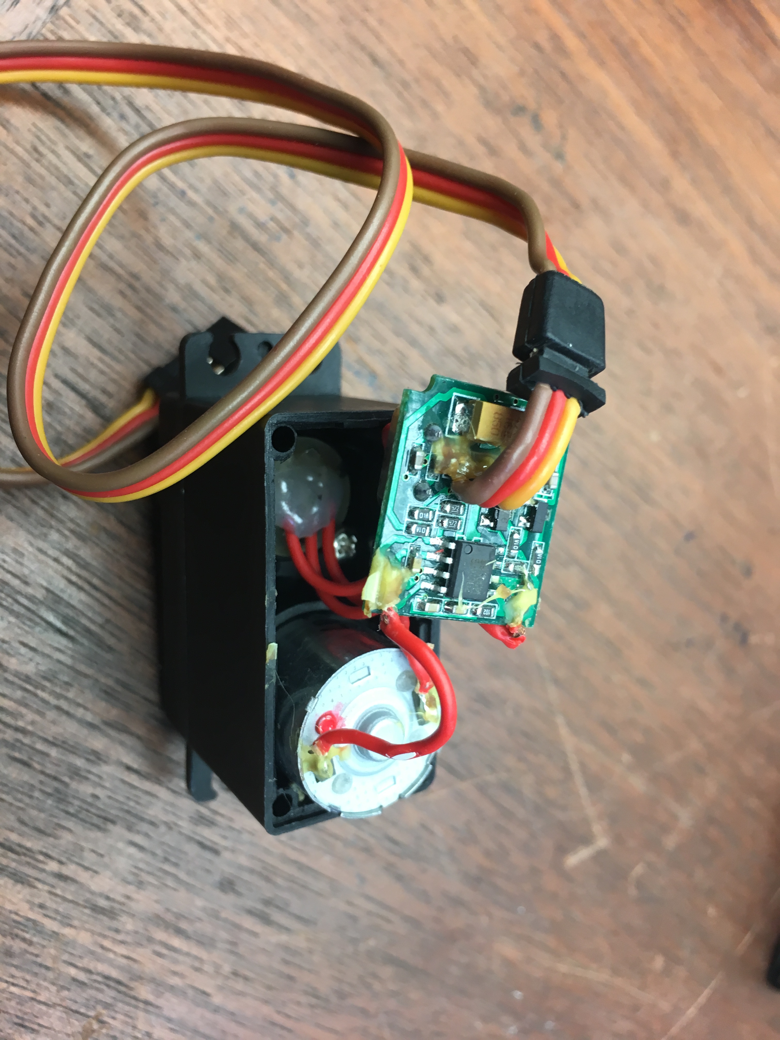
I'm finally getting close to having a Prop powered hobby servo.
The control wire will now be a 1-wire communication bus with bidirectional coms...
I went down this path before, but found I didn't have the skill set or the tools to do it: https://forums.parallax.com/discussion/124175/serial-servo-making-a-servo-more-intelligent
But now, I've learned Eagle, so I can make circuit boards thin enough to fit and my PCB design skills have improved.
Also, I have a Shapeoko CNC router so can mill the boards myself.
So, I'm gearing up to take another stab at this.
Current plan is to also add in a 3-axis accelerometer and a WS2812B in there.
This is all too much to fit on one PCB of same size as the one in this HXT12K servo.
But, there's plenty of room under the board. So plan is for a stack of two boards.
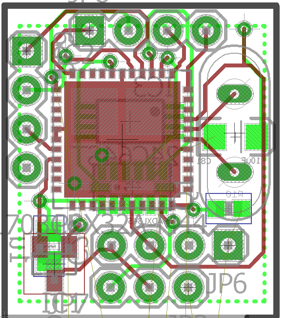
Got the layout almost done.
Top board has QFN Prop, eeprom, 3.3 v regulator, crystal, accelerometer, and prop plug port.
Bottom board has the motor driver h-bridge, transistors and resistors and soon a big capacitor.
One new thing I'm trying out is using a milled out piece of acrylic to give a hole on the back of the servo for mechanical support, turning it into a "robot servo".
The control wire will now be a 1-wire communication bus with bidirectional coms...
I went down this path before, but found I didn't have the skill set or the tools to do it: https://forums.parallax.com/discussion/124175/serial-servo-making-a-servo-more-intelligent
But now, I've learned Eagle, so I can make circuit boards thin enough to fit and my PCB design skills have improved.
Also, I have a Shapeoko CNC router so can mill the boards myself.
So, I'm gearing up to take another stab at this.
Current plan is to also add in a 3-axis accelerometer and a WS2812B in there.
This is all too much to fit on one PCB of same size as the one in this HXT12K servo.
But, there's plenty of room under the board. So plan is for a stack of two boards.
Got the layout almost done.
Top board has QFN Prop, eeprom, 3.3 v regulator, crystal, accelerometer, and prop plug port.
Bottom board has the motor driver h-bridge, transistors and resistors and soon a big capacitor.
One new thing I'm trying out is using a milled out piece of acrylic to give a hole on the back of the servo for mechanical support, turning it into a "robot servo".
3024 x 4032 - 2M
586 x 651 - 77K

516 x 650 - 50K

3024 x 4032 - 2M
Comments
I also have a ShapeOKO machine and have modified to to mill PCBs. Basically I spent a lot of time squaring it up in all axis and making sure it was absolute FLAT with a steel baseboard and T-slot rails on the baseboard ( no cheap warp prone MDF board for me!)
I use FlatCAM to do the Gerber to GCODE translation and it works very well. For the actual SpapeOKO software I use G-Code Sender Ver1.09... Again very stable and predictable, with good results every time.
Lastly, there are a few tricks of the trade (PCB layout rules, cutter tool selection, feed and speed) to make everything work - and I am willing to share if you are interested.
That way, I don't have to pay for panelization… Also, I can populate a larger board with several of these on it and then cut it out...
You can get oscillator modules, 5MHz ~ 6.5MHz that come as small as 2.0 x 1.6mm, or even (1.54mm x 0.84mm) ! if you can work BGA packages
If you are just going board-board, 2mm or even 1mm pin sticks can take up less area.
Addit: for a proven oscillator (used in FLiP), Digikey stock the SIT8918BEL13-33E-5.000000 2.5x2.0mm
- see also https://forums.parallax.com/discussion/166754/flip-here/p4 for talk around the slew options, and radiation effects. the 'BEL' is the slowest edge choice.
Smaller and well stocked looks to be DSC6001HI1A-005.0000T.
I see that DSC60xx family supports dual-clock choice, so it could be possible to use a DSC6023 with two MHz choices ?
These two MHz pairs seem popular/commonly stocked, - I wonder what uses that choice ?
DSC6023HI2A-00ADT Microchip XO 1.71V-3.63V 6.1298MHz, 6.1679MHz ±25ppm -40°C ~ 85°C 1.3mA (Typ) (1.60mm x 1.20mm) $0.90640/1k
DSC6021CI2A-00A3T Microchip XO 1.71V-3.63V 6.1298MHz, 6.1679MHz ±25ppm -40°C ~ 85°C 1.3mA (Typ) (3.20mm x 2.50mm) $0.69010/1k
https://forums.parallax.com/discussion/160864/end-of-life
and somebody pointed to Parallax's statement on this on the QFN product page:
I have a tiny crystal I could use instead.
But, as of now, I have enough space...
Ah, here it is ...
https://forums.parallax.com/discussion/comment/1292522/#Comment_1292522
" When these QFNs are gone, they're gone. I'd be happy to be in a shortage situation with QFNs because they move very slow. We will unfortunately EOL this part. The MOQ is too high for the inventory turns we have with them.
If somebody wants to order 12-25K at a time we'll build them; otherwise we can't afford to stock these.
QFNs are not preferred by contract manufacturers due to a lower yield during manufacturing.
Ken Gracey"
Are all of the 0.1" through-hole pads actually needed? I reckon single 4-layer board would be enough,
perhaps a tag-connect for programming?
Five years later, there's still 3,000 in stock...
I don't think 4-layers would help though.
(ok, I just ran into a problem where 4-layers would help... Can't get 5V over to WS2812, have to try it at 3.3v...)
The new WS2812C-2020's are designed to work in 3v3 systems.
Not 100% sure this is good enough...
If not, I'll have to drop in a digital ADC chip...