

ADC Noise
 cgracey
Posts: 14,133
cgracey
Posts: 14,133
No matter what mode I put the ADC in, for a 16-bit conversion, I get noise in the ~5 LSBs.
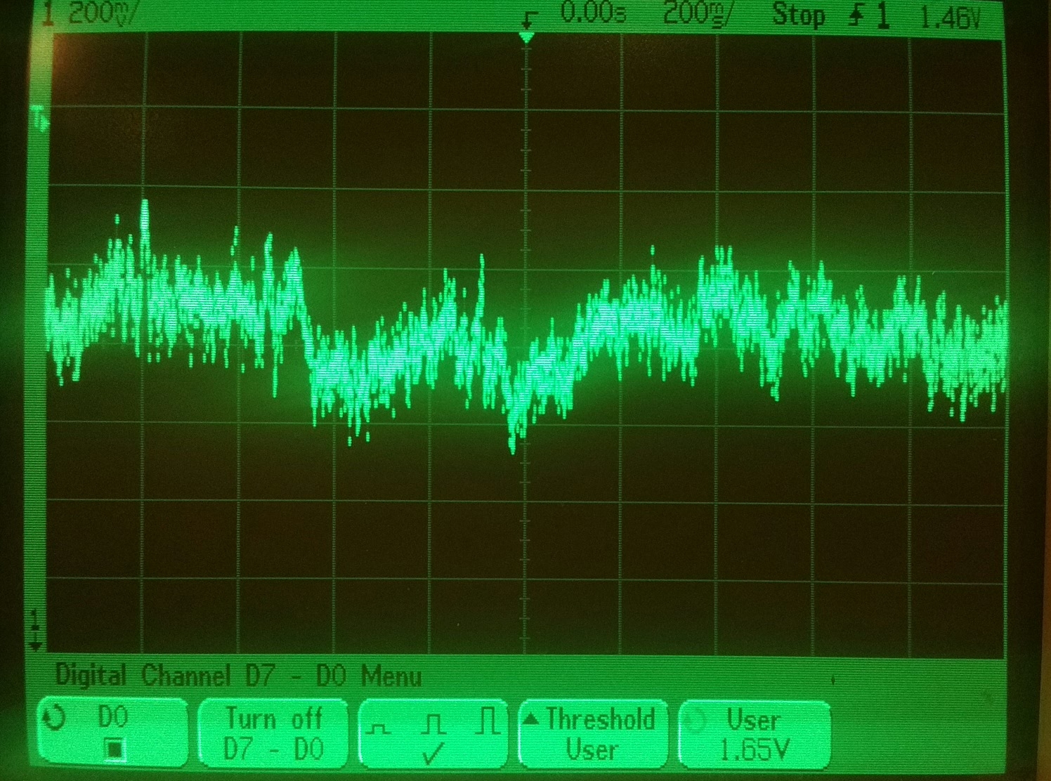
I output this noise onto a DAC, so I could look at it. It is not just hash, but a continuous noisy function. It wanders up and down. Not sure what causes it or if it can be remedied.
Here is a scope shot of it. I calculate that the peak-to-peak amplitude of this noise is ~1.6mV, or 3.3V / power(2, 16-5).
The noise amplitude stays about the same, no matter what frequency I run the chip at.
Here is my program:
' 16-bit analog to digital

con	p =	0

dat	org

	hubset	##%1_000001_0000011000_1111_10_00	'enable crystal+PLL, stay in 20MHz+ mode
	waitx	##20_000_000/100			'wait ~10ms for crystal+PLL to stabilize
	hubset	##%1_000001_0000011000_1111_10_11	'now switch to PLL running at 250MHz

'	bmask	dirb,#15

	rep	#2,#16
	wrpin	softmod,i
	add	i,#1

	wrpin	##%100000_0000000_00_01111_0,#p	'adc on
	wxpin	##$FFFF,#p
	wypin	#0,#p
	dirh	#p				'enable counter

	setse1	#%01<<6+p			'se1 triggers on adc sample

loop	waitse1					'wait adc sample
	rdpin	i,#p				'get adc sample
'	setword	outb,i,#0			'output it to P47..P32
	setbyte	dacmod,i,#1			'output lower byte of sample to P31 DAC
	wrpin	dacmod,#31
	drvl	#31
	jmp	#loop				'loop

i	long	32

softmod	long	%0000_100001001_00_00000_0
dacmod	long	%10100_00000000_00_00000_0
1496 x 1112 - 461K
Comments
16 bits is a lot...
It could be. This was about the same performance I saw on the test chip, when running it on the FPGA board.
The noise moves slowly. You can see 2 seconds' worth on the scope shot. What would have such a low time constant? I don't think it's the chip. It's encouraging to note that on nearly the 3rd vertical graticule on the scope shot, you can see the noise gets very tight briefly. This suggests that the chip will be able to resolve much better if we can get the infrastructural noise out of the situation.
In 12 hours or so, we should be able to repeat this with OzPropDev on the fully decoupled p2d2
Although, IIRC, on Flip boards the problem was related to a noisy voltage regulator.
Good idea. I will check. However, I don't think 1.6mV is going to look like much on my scope. I will try, though.
That 100mV of noise on VIO was an error. I soldered these really low-quality SIP sockets onto my P2D2 and they cause me perpetual setup headaches.
Anyway, I do see the rails coming from the bench supply wandering around like the noise pattern on the ADC does. The main noise is limited to ~10mV with ~50mV high-frequency hash.
My thoughts exactly. Not because I have an explanation but I just happened to be reading up on the 16 bit ADS1100, last night and there was a comment that, for all intents and purposes, only 13 bits are useful.
I don't have any heat or cooling like that with me.
That would be great if you could try this out, too. I suspect that if we could get quiet power, the noise floor could improve a lot.
Yes. The FFT just looks noisy, too, though.
99.9% of the time is spent waiting in the WAITSE1 instruction.
The noise I'm seeing is wandering around slowly.
Where are these long noise periods coming from? You can see that adjacent conversions are quite close, but they wander around over many samples.
I wonder what kind of effect low-frequency power-supply noise has on the ADC.
Well, these pad circuits work entirely in the VIO domain, while all the xoroshiro128** activity is in the VDD domain, probably causing some noise, but maybe none that could affect the ADCs.
I'm just outputting 8-bit DAC values without the smart pin dithering.
Wonder how that would work... 1 bit for 2 pins, 2 bits with 4 pins?
With a simple CMOS inverter element the PSRR will be a lousy 50%, so VERY CLEAN power & gnd would be needed.
I would suggest clean linear local supplies, no PLL, and a lowish MHz external OSC that is mains cycle related, so you measure over a whole mains cycle to null residual inevitable hum sources.
What is the integrator R,R,C ? (Keep sysclk high enough the integrator swings well, but does not clip.)
I do not see quiet zones ? If you you draw a histogram of the next reading deviation, that is not full swing random, but appears more step-from-last related.
That makes two adjacent equal readings more likely, so the ‘quiet’ may just be stats at work.
Well, the noise is there on internal calibration modes, where it connects the ADC input to VIO or GND.
The stumper is that the noise is very low frequency, for the most part. There is nothing in the I/O pad that should cause such a long period And it's all amounting to only 1.6mV. I think it must be coming from the VIO supply or an external ground loop.