

Precharge resistor for High Current 24V system Questions

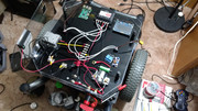
I am curious to know if a precharge resistor on a 24V 100A constant current relay can have any solder Joints (Green resistor and Metal Can Relay in the photo below lower center), I want to solder the wire to the resistor but the connection to the relay is a crimp ring. Also, do I need to use a thick guage wire, currently 8awg, or can I use a smaller guage for the resistor with a potential of 73A max according to the battery current.
Comments
This can all be prevented by the use of a precharge resistor across the contacts of the main power relay. The precharge resistor allows the capacitors in the controller to slowly charge BEFORE the contactor closes. This means that there is less voltage across the closing contacts and little or no inrush current.
Guessing that soldering the resistor is OK since that's a lower current path, and likewise somewhat smaller wire is OK. Guess there's no fuse or circuit breaker here. How much current do you actually expect? 100A is very serious stuff.
I expect no more than 20A on the relay unless there is a stall condition (oops wall), I am trying to mitigate that with sensors that will cut power to the motor controller if needed, thats what one of relays are to be used for on the dual relay board, just above the metal can (Constant High Current).
I ask because I could not find definitive answers through google and I have never done high current wiring. Just want to prevent some smoke effects
In order to consciously give you the level of help you need, and deserve, its important (at least to me) to know some facts about your circuit:
- What is the value of the precharge resistor (to determine the value of the maximum current flowing thru it, e.g., in the event of a shorted wiring or motor)?
- Have you thinked about adding another relay, in series with the precharger resistor, so as to avoid the load (motor) to be constantly (but with a low current flow) powered thru the precharge resistor (to determine the level of power constantly being dissipated by the precharge resistor, hence determining its body/terminals minimum expected temperature under steady open air conditions)?
- The type of resistor (make, model) to help estimate the above mentioned body/terminals temperature)?
Henrique
The precharge resistor is 5 Ohm 50 Watt
Yes, I want to keep this part of the circuit without a relay on the resistor. It allows enough current to power the MCP263 (ION Motion Controller) but not quite enough to power the motors with. Atleast for now, I will end up getting an additional battery, like Parallax's 12V SLA, to power the electronics but not the motors. I have not tried to power the motors this way but I should probably test it with IONMC's software. I am considering mounting this resistor onto a steel plate if I notice it heating up significantly.
I bought this off of amazon.com because I was already placing an order. I recieved it from uxcell and I have not been able to find the datasheet for it. Uxcell PN: a12050400ux0155
Wow! @24Vdc and considering a 5 Ohm resistor, it gives 4.8A, in case of a short-circuit condition. Since Uxcell PN: a12050400ux0155 available data (at their website) shows +-5% tolerance at resistance values, then 24 / 4.75 = 5.05A.
uxcell.com/watt-ohm-green-aluminum-shell-wire-wound-resistor-p-211625.html
From your description of the circuit, that 5.05 A current would not trip (nor fuse) any protection, then the resistor would have to be able to dissipate 5 x (5.05 ^ 2) = 127.65W (short circuit condition).
From Uxcell specs, "Note: For longer service life, the actual load power connected to this product should be less than 70% of the rated power". Thus, minimum rated power should be: 127.65 / 0.7 = 182.4W, in other words, roughly four times the one you have.
Without having a full-featured datasheet for the part you have in hand, I'll resort to Vishay (Dale) equivalent ones (at least in resistance/power/housing). Known to be one of the best in that specific market, you could expect the one you bought to have at least similar specs (pray, at least).
vishay.com/docs/31806/tmc.pdf
From Vishay datasheet, the maximum working voltage for a part like the one you have, should be restricted to (P x R) ^1/2 or (50 x 4.75) ^1/2 = 15.4V. If we consider a 182.4W, the same maths would lead to (182.4 x 4.75) ^1/2 = 29.4Vdc, which is compatible with your actual power supply.
IMHO, you slould consider using a parallel association of two 100W, 10Ohms parts, or four 50W, 20Ohms ones, to meet the safe side of the available specs.
There is no data available for the temperature raise at the terminals, but, considering the power levels involved, it is advisable to ensure both good mechanical and electrical connections between the wires and the terminals, to avoid melting the solder joints, in the event of a short circuit event.
And sure, you'll don't need #8 AWG wire for such values of current (~5A); #18 AWG (7A) will do it nicely, even derating it by almost 30%. Also its ~1mm diameter would best fit the holes at the terminals, enabling double twisting, to ensure good mechanical connections.
As for the heat-spreading sheet metal, always remember; providing ample area for heath spreading does remedy the body temperature raise, but don't avoid the core to be significantly hotter than the body itself, and the terminals are directly attached to the core, thus, you should expect they to closely follow its (core) temperature.
In other words, your fingers will notice (burn) well before your eyes could see any magic smoke, unless some solder paste residues would be left, uncleaned, at the soldered terminals.
Henrique