

P1V - My new COG/HUB RAM concept
 Cluso99
Posts: 18,069
Cluso99
Posts: 18,069
I have been playing with some FPGAs recently. So I thought I would try my hand again with the P1V. This concept should work with smaller FPGAs, just with less RAM to spread around. Here is the concept, picture first.
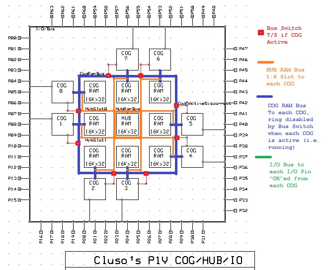
This is how it works...
There are 9 Blocks of 64KB (16Kx32) RAM, arranged as 32bits wide, accessable as bytes/words/longs, on long boundaries (same as HUB RAM in P1). If there is less RAM available in the FPGA, then 9 blocks of a smaller size. If less that 8 cogs, then the number of RAM Blocks will be the number of COGs +1.
The Central RAM Block forms the HUB RAM. This is accessable by each COG in turn, with each COG getting a turn (time slot) every 8 clocks (was 1:16 for P1).
The 8 remaining RAM Blocks have a Data & Address Bus running around the outside. Each of the 8 COGs have their Data & Address Bus connected to this Bus Ring.
This outer ring of Data & Address Bus has gate/switches to isolate each RAM Block. Each RAM Block is connected to this Ring Bus, and to its' respective COG. If all isolators were active, then each RAM Block would only be connected to its' respective COG.
On Power Up or Reset, COG-0 is started (becomes active). No other COG is active (running).
When a COG becomes active, it automatically turns its' Bus Isolator switch ON (i.e. the bus is isolated at this respective point).
The effect of these isolation switches is such that when only a single COG is active, that COG will own ALL 8 RAM Blocks. (i.e. 8*64KB=512KB)
For example, COG-0 when active cuts the Bus between COG-0 & COG-1. COG-0 will have its' own 64KB RAM Block at $0_0000-$0_FFFF, plus COG-7's RAM at $1_0000-$1_FFFF, plus COG-6, 5, 4, 3, 2 and COG-1 at $8_0000-$8_FFFF.
Now when COG-1 becomes active, it isolates the Bus between it and COG-2, so it will only get 1 RAM Block at $0_0000-$0_FFFF, and COG-0 will lose access to COG-1's RAM at $8_0000-$8_FFFF.
By starting specific COGs, while leaving other COGs inactive, it is possible to dish out various size COG RAMs to respective COGs.
Note that each COG now has large COG RAM, with the Program Counter extended to 20bits (to address 1MB max). Since these RAM Blocks are straight COG Memory, code can execute from the large COG RAM without penalty. It will be necessary to introduce a method (instruction variants) for accessing the larger COG Memory. For example...
A new JMPRET instruction where the jump/return registers (S & D) contain the 20-bit memory addresses. i.e. an INDIRECT JUMP/CALL instruction
A new MOV instruction where the S and/or D registers contain the 20-bit memory addresses. i.e. an INDIRET MOV instruction
Other methods are possible using an AUGDS instruction.
660 x 544 - 118K
Comments
That would need some special handling/rules for self-modifying code, as only the original the base area can overlay regs and code.(rest is code-only)
OR, you could split that so half is common/global Data, and then multiple banked upper halves can be local data/code.
OR, you could use a Register Frame Pointer, like Z8 & C166, which could move COGs 512W thru the memory map, on some smaller granularity to allow param passing..
Some map bits could then lock some portion of Bank0 as global/shared data. (1/2, 1/4, 1/8, 1/16 etc)
One down side of memory, is larger memory tends to be slower, so you would need to check bigger memory and muxes did not push the SysCLK down too much.
Please forgive me if I've completely misunderstood how this works. But I see (at this time) 3 possibilities of how this would work.
Listed in order of perceived likelihood.
In all cases, at startup, by default, COG-0 is started and gets all of the RAM Blocks.
(Case 1)
Then you start COG-1, and it gets its RAM Block (1), and COG-0 now has access to RAM blocks 0, 2, 3, 4, 5, 6, and 7.
So COG-1 has 64k of RAM and COG-0 now has 7*64=448k of RAM.
At this point, how do I assign (and isolate) RAM Block 2 to COG-1 so that it has 128k of RAM and COG-0 has the remaining 384k of RAM? Is this possible in your design?
Or (Case 2)
COG-1 is started.
Is it that each cog is assigned its own RAM Block at startup and all unassigned RAM Blocks (2-7) are now available to both COG-0 and COG-1? Unlikely due to issues with atomic memory operations.
Or (Case 3)
If I instead start COG-4 then would it be assigned its RAM Block and all that follow (a total of 4 blocks), and COG-0 would then have access to only the first 4 blocks? This implies that starting a cog activates the Bus Isolator switches for the cog and any unlocked RAM Blocks between the cog and the next activated cog.
Something like this?
SW0 = Bus Isolator Switch 0, and so on.
At boot:
COG-0 ("C-0") is started:
Now COG-0 has access to all RAM Blocks.
COG-4 is started:
Is it now implied that the RAM Blocks controlled by SW0 through SW3 are now not accessible from COG-4? And the same for COG-0, it cannot access the RAM Blocks controlled by SW4 through SW7?
Finally, can a cog turn its activation switch off?
Interesting concept!
Walter
Please forgive me if I've completely misunderstood how this works. But I see (at this time) 3 possibilities of how this would work.
Listed in order of perceived likelihood.
In all cases, at startup, by default, COG-0 is started and gets all of the RAM Blocks.
Yes
(Case 1)
Then you start COG-1, and it gets its RAM Block (1), and COG-0 now has access to RAM blocks 0, 2, 3, 4, 5, 6, and 7.
So COG-1 has 64k of RAM and COG-0 now has 7*64=448k of RAM.
No. COG-0 has access to blocks 0,7,6,5,4,3,2 (448KB) in that ascending address order.
That's why the isolation switch is between this cog and the next one.
At this point, how do I assign (and isolate) RAM Block 2 to COG-1 so that it has 128k of RAM and COG-0 has the remaining 384k of RAM? Is this possible in your design?
You can't. Just start COG-2 instead of COG-1, and it gets blocks 2,1 (128KB) and COG-0 has 0,7,6,5,4,3 (384KB).
Or (Case 2)
COG-1 is started.
Is it that each cog is assigned its own RAM Block at startup and all unassigned RAM Blocks (2-7) are now available to both COG-0 and COG-1? Unlikely due to issues with atomic memory operations.
No. Each COG will have its' own block when started, plus any lower free/unclaimed blocks.
Or (Case 3)
If I instead start COG-4 then would it be assigned its RAM Block and all that follow (a total of 4 blocks), and COG-0 would then have access to only the first 4 blocks? This implies that starting a cog activates the Bus Isolator switches for the cog and any unlocked RAM Blocks between the cog and the next activated cog.
Something like this?
SW0 = Bus Isolator Switch 0, and so on.
At boot:
COG-0 ("C-0") is started:
Now COG-0 has access to all RAM Blocks.
COG-4 is started:
Is it now implied that the RAM Blocks controlled by SW0 through SW3 are now not accessible from COG-4? And the same for COG-0, it cannot access the RAM Blocks controlled by SW4 through SW7?
Basically you are on the right track. But, each COG automatically sets its' isolator switch to isolate when it is running. The switch is set by the hardware when a cog starts and stops.
Next, the cogs get each lower successive block of ram if those lower cogs are not running (i.e. not the next higher cog blocks).
Finally, can a cog turn its activation switch off?
No. It is controlled by the hardware.
Interesting concept!
Walter
Think I have worked out how to...
1. Use Dual Port Cog RAM
2. Combine read S and D states (most instructions will be 3 clocks instead of 4
3. Combine read I while writing R (most instructions will then be 2 clocks)
This plus hub being 1:8 clocks, should give a nice boost, providing I can get the timing correct.