Shop OBEX P1 Docs P2 Docs Learn Events
Losing the touch - how to modify LED light fixture to bypass touch on/off — Parallax Forums

Losing the touch - how to modify LED light fixture to bypass touch on/off

I've bought a led lighting fixture to have above the kitchen bench (one of several). It is a LED strip and fits the purpose perfectly - if it was not for the touch toggle on/off function on every fixture. I want one, central switch for all of them. Looking inside I found BC83B08A-3 MCU which handles the touch signal, and a 4406a GA5N2P which I assume is some sort of constant current regulator. There are more circuits, but I believe these two hold the key. Problem is, it is very difficult to identify the pcb tracks, and secondly, I can not find a datasheet for the 4406a GA5N2P. I think the BC83B08A-3 is outputting a PWM, but since it would be 100% when on, I am thinking I can just tie this signal high. But this is too much guesswork for the cost of a potentially burned fixture. Anyone done this before?

Erlend

Comments

  • kwinnkwinn Posts: 8,697
    edited 2017-02-25 17:53
    Typical touch switches sense the 50/60Hz your body picks up when you touch the plate or housing. You could try a high level DC signal or low voltage AC signal through a 1M or 100K resistor. It will probably need to be a momentary signal, so an on/off push button.
  • kwinn wrote:
    It will probably need to be a momentary signal, so an on/off push button.
    That would probably work, but how to keep all the lights synchronized? IOW, press the button, and half of them come on, while the other half that were already on, turn off. Or, if you release the button too quickly, some of them respond, while the others do not.

    -Phil
  • kwinnkwinn Posts: 8,697
    kwinn wrote:
    It will probably need to be a momentary signal, so an on/off push button.
    That would probably work, but how to keep all the lights synchronized? IOW, press the button, and half of them come on, while the other half that were already on, turn off. Or, if you release the button too quickly, some of them respond, while the others do not.

    -Phil

    Depends on how much of a problem that is. Also need to test for typical power situations like long and brief outages, on/off flickering, and solid off to on switching. If signal timing is critical that could be solved with a 555 timer. One way to find out is to try it with multiple units.

    If the 4406a GA5N2P is a constant current regulator (which seems likely as searching had it mentioned as a battery charge chip) then perhaps the signal from the BC83B08A-3 could be replaced with a switch.

  • If I could only figure out the 4406a GA5N2P I could probably force high a pin and make it be ON as long as there is mains power. I would rather avoid adding new circuitry (to 5 fixtures) such as 555 an the like.

    Erlend
  • What happens when you first power the fixtures on? Light on? Light off? Random?

    -Phil
  • kwinnkwinn Posts: 8,697
    What happens when you first power the fixtures on? Light on? Light off? Random?-Phil
    This is the first thing to check out. If it consistently powers up with the light off (as it should IMHO) or on then we can proceed to the next step.
    Erlend wrote: »
    If I could only figure out the 4406a GA5N2P I could probably force high a pin and make it be ON as long as there is mains power. I would rather avoid adding new circuitry (to 5 fixtures) such as 555 an the like.

    Erlend

    If step one gives a consistent off or on you can connect a wire from a switch or 555 to the "touch" area and see if that works. If a DC signal works you are good to go. If it requires an AC signal you may need a 555 or 556 to produce the signal.
  • kwinnkwinn Posts: 8,697
    One question. Does this light strip run off the 240VAC line or an AC adapter of some kind?
  • ErlendErlend Posts: 612
    edited 2017-02-26 08:11
    The strip runs off 12V from a mains adaptor. I first tried to tie the touch input to 12V through a MOhm resistor, but that had no effect. Then I measured the voltage of every pin of the MCU with lights off and lights on, and found a pin that went high with the light. Soldered that pin to a pin with constant 5V on it - and that worked!

    LED_fix.jpg

    Of course there are plenty of other things I should instead spend my weekend on, but if you're a tinker...

    Erlend
  • MikeDYurMikeDYur Posts: 2,176
    edited 2017-02-26 14:34
    Can you post a schematic? It seems like your best bet is to remove components or cut traces. But you need to bypass, or get rid of the touch switch circuitry.


    BTW: Your picture "LED_fix.jpg" failed to load.
  • ErlendErlend Posts: 612
    edited 2017-02-26 15:13
    The picture shows the fix I did:
    LED_fix.jpg

    Jumper from pin 8 to pin 10.

    Erlend
  • i solved the problem that Erlend proposed.thank you. I soldered the2 pins as shown in the picture.The voltage between these two pins is 5V when the light is turned on.If you put the black probe on one pin and red probe on the other you get 5 V.

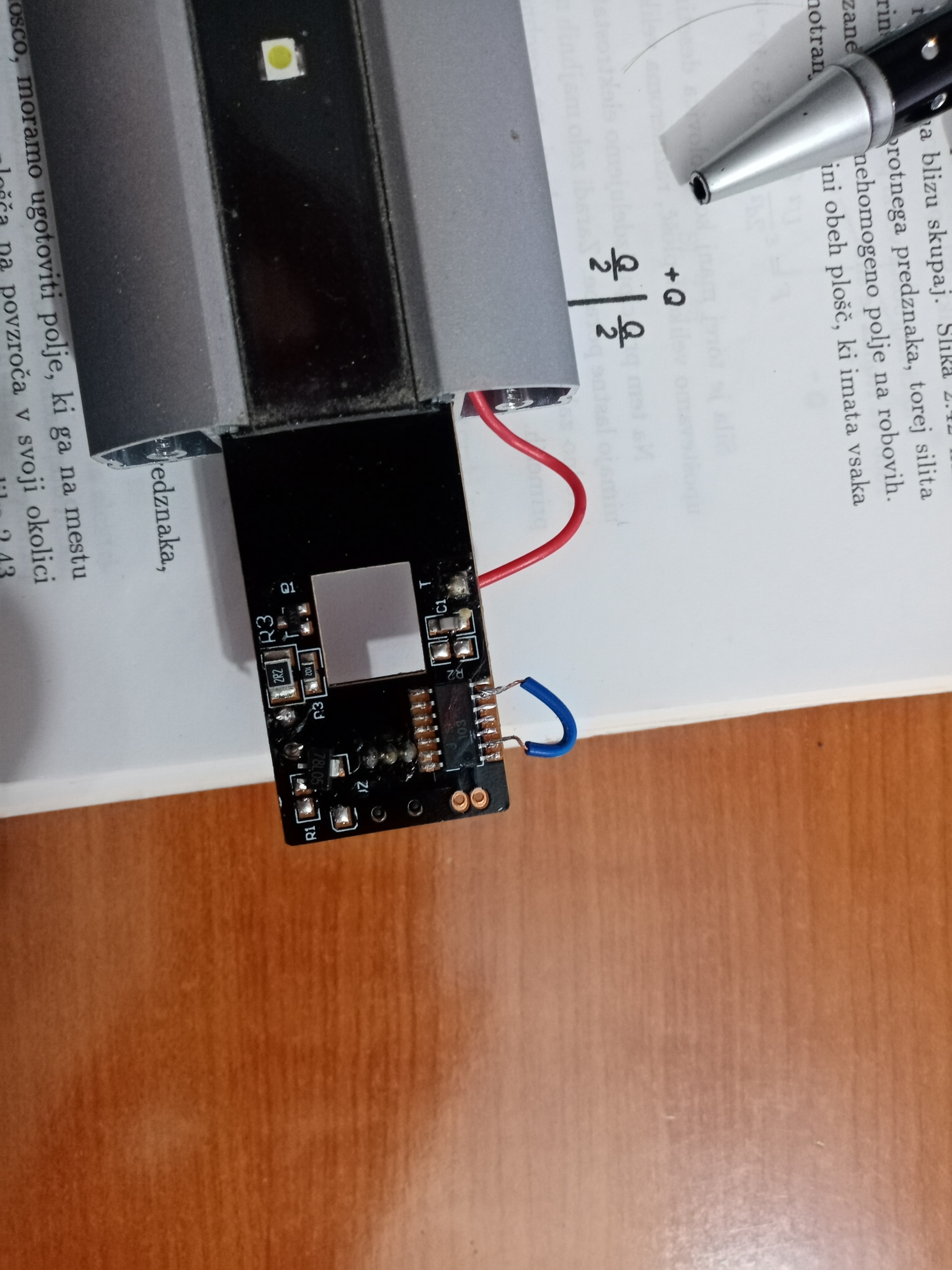
  • i unsoldered the red wirre which goes to touch sensor then.But works also with the red wire attached to the touch sensor.That was the case with this LED Lamp.

Sign In or Register to comment.