

Need help to figure out a test for an late 80's transistor ignition
 Capt. Quirk
Posts: 872
Capt. Quirk
Posts: 872
The biggest problem is that I don't have all the parts. So I am trying to figure out
a theoretical test that I can recommend to others.
The missing part is a pick-up sensor for a transistor ignition. It uses 2 magnets.
One to trigger the dwell and the second to fire the ignition coil. I am assuming the
2 magnets consist of a separate north & south pole.
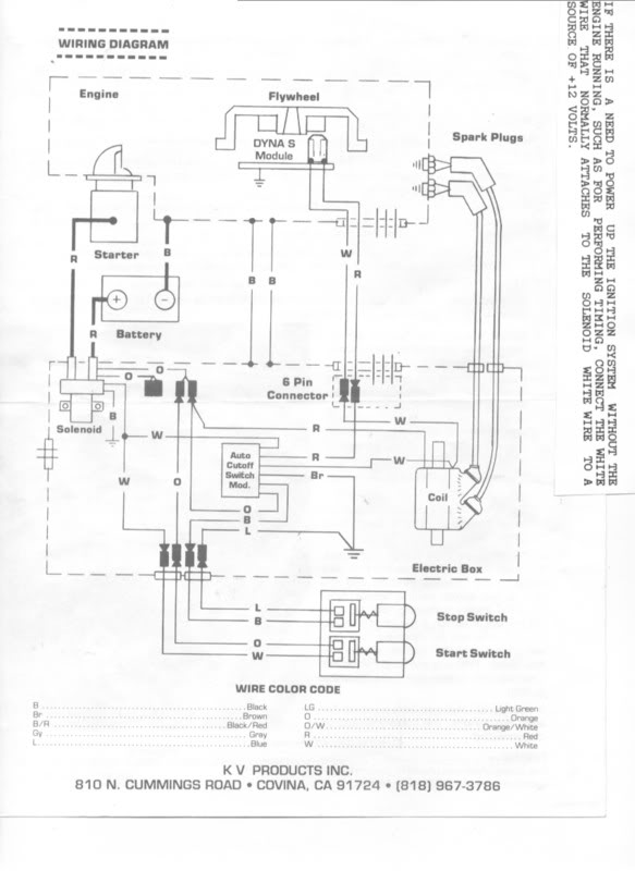
The pick-up assembly has 2 wires and grounds to the engine through the stator plate.
One wire is the negative lead from the coil, and the other is 12v. If you look at the wire
diagram I supplied, the Red wire is 12v, and the White wire is the ignition coil ground.
This is where I need your help. (1) I believe the hall effect sensor is a latching type.
Did they have Latching hall sensors around 1985? Most of the old data sheets I have
looked at describe hall sensors that idle at 1/2 vdd (unless they are pulled high or low)
and then rise or fall +/- 1/2 vdd when the magnet passes by.
(2) I believe the latching hall sensor is supplying the transistor base with 12v, then
negative lead from the coil has a path to ground and dwell begins.
(3) Then the opposite magnet pole triggers the hall sensor to stop supplying the
transistor base with 12v. Then the ignition coils field collapses and the spark is
produced.
(4) I believe the 12v lead to the pick-up sensor supplies only the hall sensor.
(5) To test this, I believe that if the stator plate is removed, and no longer grounded
to the engine, but all the wires still connected to the battery and the ignition coil. I
could measure the current from the sensor to engine ground.
The down side to this is the ignition coil will most likely produce a spark when
you disconnect the multi-meter. Another problem is the possibility of overheating
the coil while trying to perform the test? These old transistor ignition coils failed
often when you left the power switch on. Test #5 would also need a known good
ignition coil.
(6) Next idea: Remove the negative wire from the ignition coil and hook it directly
to the battery. The stator plate would still need to be removed, but the lead that
supplies 12v would still be connected.
Then hook up a multi-meter to test for 12 volts from the bottom of the sensor,
and using the engine as a ground when the proper magnet is passed over the
sensor I should see 12v. I suppose a test light, or an old brake light lead would
work too?
(7) If latching hall sensors did exist, is it possible the sensor would be stuck on
or off after the stator plate is removed? Do they only reset after an opposite pole
has passed by, or do they reset after a period of time, or loss of a power source?
If the latching hall sensor does not reset by itself, then I would need to reset it
before the test? or if it shows 12v, do I need to reset it to prove the hall sensor
is capable of latching, and it still works?
What would be the part that is most likely to fail? the hall sensor or transistor?
One last thing, is there a reed switch equivalent to a latching hall sensor?
Thanks for your input!
Bill M.
a theoretical test that I can recommend to others.
The missing part is a pick-up sensor for a transistor ignition. It uses 2 magnets.
One to trigger the dwell and the second to fire the ignition coil. I am assuming the
2 magnets consist of a separate north & south pole.
The pick-up assembly has 2 wires and grounds to the engine through the stator plate.
One wire is the negative lead from the coil, and the other is 12v. If you look at the wire
diagram I supplied, the Red wire is 12v, and the White wire is the ignition coil ground.
This is where I need your help. (1) I believe the hall effect sensor is a latching type.
Did they have Latching hall sensors around 1985? Most of the old data sheets I have
looked at describe hall sensors that idle at 1/2 vdd (unless they are pulled high or low)
and then rise or fall +/- 1/2 vdd when the magnet passes by.
(2) I believe the latching hall sensor is supplying the transistor base with 12v, then
negative lead from the coil has a path to ground and dwell begins.
(3) Then the opposite magnet pole triggers the hall sensor to stop supplying the
transistor base with 12v. Then the ignition coils field collapses and the spark is
produced.
(4) I believe the 12v lead to the pick-up sensor supplies only the hall sensor.
(5) To test this, I believe that if the stator plate is removed, and no longer grounded
to the engine, but all the wires still connected to the battery and the ignition coil. I
could measure the current from the sensor to engine ground.
The down side to this is the ignition coil will most likely produce a spark when
you disconnect the multi-meter. Another problem is the possibility of overheating
the coil while trying to perform the test? These old transistor ignition coils failed
often when you left the power switch on. Test #5 would also need a known good
ignition coil.
(6) Next idea: Remove the negative wire from the ignition coil and hook it directly
to the battery. The stator plate would still need to be removed, but the lead that
supplies 12v would still be connected.
Then hook up a multi-meter to test for 12 volts from the bottom of the sensor,
and using the engine as a ground when the proper magnet is passed over the
sensor I should see 12v. I suppose a test light, or an old brake light lead would
work too?
(7) If latching hall sensors did exist, is it possible the sensor would be stuck on
or off after the stator plate is removed? Do they only reset after an opposite pole
has passed by, or do they reset after a period of time, or loss of a power source?
If the latching hall sensor does not reset by itself, then I would need to reset it
before the test? or if it shows 12v, do I need to reset it to prove the hall sensor
is capable of latching, and it still works?
What would be the part that is most likely to fail? the hall sensor or transistor?
One last thing, is there a reed switch equivalent to a latching hall sensor?
Thanks for your input!
Bill M.
583 x 800 - 55K
Comments
http://forums.parallax.com/discussion/165992/i-need-some-advice-on-interfacing-a-12v-20-duty-cycle-to-a-propeller-pin#latest
I may have to merge it with that post. Sounds like a double post.
It is completely different. Two separate ignition systems, two separate problems and each
were posted where they belong.
Bill M.
My data sheets newer ignitions (late 80's) for the Vane Hall sensors used a hall sensor that triggers a transistor. The pick-up uses 2 magnets
and some sort of current switch.
Is it possible to use a hall effect sensor to to turn on and off a SCR?
From what I have read in old Honeywell data sheets, some of their hall sensors for ignition systems were capable of going high or low depending
on magnet polarity. I have read similar characteristics from Allegro. Is it possible to turn an SCR on and off with a bi-polar hall sensor?
Bill M.
SCR's can be gated on by a hall sensor but they only turn off when the current between the anode and cathode is below the minimum holding current level. For a CD ignition circuit this happens when the capacitor has been fully discharged through the ignition coil primary winding.
old titanium flywheel that used only a single magnet/180'. That module is easy to figure
out.
I have another photo I found on Google, that shows a two magnet/180' flywheel. That
pick-up assembly is a mystery to me.
Bill M.