

Blind Spot Warning project
 Chet
Posts: 150
Chet
Posts: 150
in BASIC Stamp
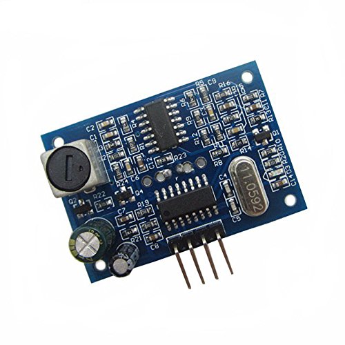
I recently bought two waterproof ultrasonic sensor boards off Amazon for a blind spot monitoring system for my car. I have a bunch of homework boards and thought I could put one of them to use this way.
Image:
https://images-na.ssl-images-amazon.com/images/I/51Ezu+lAyQL.jpg
I plucked the core part of the code below from "Garage Parking Assistant V1.1.bs2" written by Chris Savage.
The instructions published about the boards are:
The basic working principle:
1) using IO port TRIG trigger location, to the high level signal at least 10us.
2) module automatically sends 8 40KHz Fang Bo, automatic detecting whether a signal return.
3) A signal return, a high level is output through the IO port ECHO, the time duration of the high level is ultrasonic from launch to return.
The test distance = (high level time x speed of sound (340M/S)) /2.
When I run the program, it shows 0 inches although the nearest object is 6 feet from the transducer.
I did write a test program that reads the level of the echo port after the PULSIN statement. It showed that the echo port was low and went to high and back to low.
The maximum expected input pulse is less than 40.000 uS.
CODE:
' blindspot_test1`.bs2
' This program sends a 10us high pulse to trigger pin
' the reads pulse width high from echo pin
' {$STAMP BS2}
' {$PBASIC 2.5}
' {$PORT COM3}
'
[ I/O Definitions ]
PING PIN 15 ' trigger pulse to Sensor
ECHO PIN 14 ' Distance pulse
'
[ Constants ]
Trigger CON 5 ' Trigger Pulse = 10 uS
Scale CON $200 ' Raw x 2.00 = uS
RawToIn CON 889 ' 1 / 73.746 (with **)
RawToCm CON 2257 ' 1 / 29.034 (with **)
IsHigh CON 1 ' Logic State Is HIGH
IsLow CON 0 ' Logic State Is LOW
'
[ Variables ]
rawDist VAR Word ' Raw Measurement
inches VAR Word ' Distance In Inches
cm VAR Word ' Distance In Centimeters
'
[ EEPROM Data ]
'
[ Initialization ]
'
[ Program Code ]
Main:
DO
GOSUB Get_Sonar ' Get Current Distance
DEBUG HOME, "INCHES: ", DEC inches, CLREOL
'DEBUG HOME, "CENTIMETERS: ", DEC cm, CLREOL
PAUSE 200
LOOP
'
[ Subroutines ]
Get_Sonar:
Ping = IsLow ' Make Trigger 0-1-0
PULSOUT Ping, Trigger ' Trigger PING)))
PULSIN Echo, IsHigh, rawDist ' Measure Echo Pulse
rawDist = rawDist */ Scale ' Convert To uS
rawDist = rawDist / 2 ' Remove Return Trip
inches = rawDist ** RawToIn ' Convert To Inches
cm = rawDist ** RawToCm ' Convert To Centimeters
RETURN
Thanks for having a look.
Merry Christmas, Happy Hanuka and Happy Holidays
Comments
From what I can garner, the unit functions as follows:
Pulse the trigger high for at least 10uS
Then there are sound pulses (8 40KHz pulses) emitted by the unit.
After the ultrasonic output, it starts measuring the time it takes for the sound return and expresses that as the echo pulse. Echo should go high as soon as the ultrasonic pulse is completed and go low as soon as the reflection is detected.
My first though was that I was not fast enough to pic up the leading edge of the 0 to 1 transition of the echo pulse.
I then wrote a short program that just input the value of the echo line and can confirm that it is briefly low after the pulsin and then goes high and back to low. I do not have a scope to get the exact times of the pulses however.
The general function from what I can tell is very similar to the PING unit. I got these because i need the single waterproof transceiver to put in the bumper.
I did the "DEBUG DEC rawDist" but that also showed zero as well. Unfortunately I gave away my scope a couple years ago to an electronics student who needed one. Now that i have time to "fool around" with this stuff again, i might have to find a replacement scope.
Get_Sonar:
Ping = IsLow ' Make Trigger 0-1-0
PULSOUT Ping, Trigger ' Trigger PING)))
RCTIME echo, 1, rawDist ' <<< change
' PULSIN Echo, IsHigh, rawDist ' Measure Echo Pulse
rawDist = rawDist */ Scale ' Convert To uS
rawDist = rawDist / 2 ' Remove Return Trip
inches = rawDist ** RawToIn ' Convert To Inches
cm = rawDist ** RawToCm ' Convert To Centimeters
RETURN
Two questions come to mind:
Does this sensor output a pulse whose width varies with the echo time, or is it the time between the trigger pulse and the received echo pulse that determines the distance.
The BS2 executes about 4000 instructions per second, or 250uS per instruction. Is that fast enough?
Hard to say without a data sheet or a scope to measure the timing.
An alternative might be to try is with a 50 MHz SX. I have a few of those somewhere.
Thanks for your feedback
The RCTIME command compensates for the "loss" of the zero to one for the distance. pulse. Since that time is constant for every try, it should work for the purpose of determining the distance (relatively).
The alternatives I have are using the propeller and have one cog start looking for the distance pulse before doing the PULSOUT on another cog to measure the distance pulse. The only problem is that my propping is not up to snuff. There is also the BS24P, which i have sitting around as well (12000 ips vs 4000 ips). The basic for the sx has roughly the same timing from what I can gather.
I`ve used exaktly the same code as your original post for my 4-pin ultrasonic sensor, type HC-SR04. That worked allright for me with the BS2, so I had a look at my code today to compare with yours. It`s all the same exept that my constant Scale is set to $1D1 (465), and your Scale is set to $200 (512). Could that make any real big difference? When you tried this, did you make sure disable the DEBUG line in the main loop so this one did`nt owerwrite the DEBUG line in the Get_Sonar routine? They both have the HOME instruction..
You shoud maybe also try to debug the rawDist in your original code with PULSIN instead of RCTIME.
The funktion of my HC-SR04 is exactly the same as you describe for your sensor, so this should be working. Yes. Mine do so. Longer pulse with= longer distance.
PS. I`m not an expert at the BS2, but I just thought I would share my experience with this code. Hope it helps.
The RCTIME command compensates for the "loss" of the zero to one for the distance. pulse. Since that time is constant for every try, it should work for the purpose of determining the distance (relatively).
The alternatives I have are using the propeller and have one cog start looking for the distance pulse before doing the PULSOUT on another cog to measure the distance pulse or the BS24P, which i have sitting around as well (12000 ips vs 4000 ips). The basic for the sx has roughly the same timing from what I can gather.
I have confirmed that the zero to one transition echo pulse comes about 220 uS after the fall of the trigger pulse. The PULSIN instruction execution apparently just misses the zero to one transition of the echo pulse.
I do wonder if outputting a high or low on the BS2 is faster than a pulsout. If so, and the ping is edge triggered then outputting a high or low on the trigger pin followed by a pulsin, and then a low or high to restore the trigger pin to it's default state might work.
Thanks for your suggestion.
Have a happy safe new year.
Unfortunately, I gave my scope to an Electronics student a few years ago. Apparently the unit I am using does not have that long a hold-off time. From some tests I have done, the "hold-off time is less than 250uS. I have settled on using the RCTIME code to determine the distance. I am not looking for absolute measurements in this case. I will simply determine what distance is coupled to the level of warning. It is kind of a red and yellow indicator. If I turn on the directional signal and there is a car in the blind spot, there will be a BEEP and a red LED will light in the respective outside mirror. I thought it would be interested after having seen it on my wife's Mercedes. (My car is pre-modern tech - part of the reason I like it...)
Valuable tool for many reasons. Not just timing, but protocol decoding and communications verification/feedback.