

Propeller Powered From Non-Isolated 120VAC Power Input - Prop Plug Acting Sketchy/Not Working Right
 Mahonroy
Posts: 175
Mahonroy
Posts: 175
in Propeller 1
Hey guys,
I have a propeller device that is powered from a non isolated 120VAC to 12VDC power converter module:
http://rohmfs.rohm.com/en/products/databook/datasheet/module/power_module/acdc_converter/bp5067-12.pdf
I then am using a 3.3VDC voltage regulator (RECOM R-78E3.3-0.5):
http://www.mouser.com/ds/2/468/R-78Exx-0.5-21170.pdf
Here is an image of the power rail schematic for my circuit:
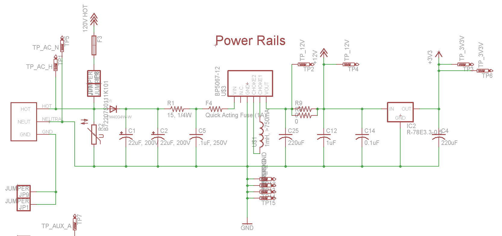
I have a feeling that this has to do with using the neutral line as the ground in my schematic. This is also the same ground that the prop plug uses. I notice that with the device powered down, plugging in the prop plug, that the prop plug led stays constantly lit. Sometimes I can detect the propeller chip, and sometimes the serial terminal works and receives messages from the device. Other times the prop terminal and the propeller tool will freeze and I have to unplug and re-plug in the USB prop plug to get it to work again. Using the prop plug on other propeller devices work just fine, so I have a feeling its something to do with this specific design.
Am I missing something? Is there something that I should do differently with my schematic so that I can use the prop plug while this thing is connected to 120VAC?
If I power only the 3.3v rail of my device externally with a wall wort (leaving the device unplugged from 120VAC), the prop plug works perfectly fine (and the device works perfectly fine without the prop plug plugged in)... it only malfunctions when I actually plug the device in with the prop plug.
So I think it has to do with the neutral line. If someone could give me an explanation and possibly a fix that would be great, as I do not fully understand the problem. Any help is greatly appreciated, thanks again!
I have a propeller device that is powered from a non isolated 120VAC to 12VDC power converter module:
http://rohmfs.rohm.com/en/products/databook/datasheet/module/power_module/acdc_converter/bp5067-12.pdf
I then am using a 3.3VDC voltage regulator (RECOM R-78E3.3-0.5):
http://www.mouser.com/ds/2/468/R-78Exx-0.5-21170.pdf
Here is an image of the power rail schematic for my circuit:
I have a feeling that this has to do with using the neutral line as the ground in my schematic. This is also the same ground that the prop plug uses. I notice that with the device powered down, plugging in the prop plug, that the prop plug led stays constantly lit. Sometimes I can detect the propeller chip, and sometimes the serial terminal works and receives messages from the device. Other times the prop terminal and the propeller tool will freeze and I have to unplug and re-plug in the USB prop plug to get it to work again. Using the prop plug on other propeller devices work just fine, so I have a feeling its something to do with this specific design.
Am I missing something? Is there something that I should do differently with my schematic so that I can use the prop plug while this thing is connected to 120VAC?
If I power only the 3.3v rail of my device externally with a wall wort (leaving the device unplugged from 120VAC), the prop plug works perfectly fine (and the device works perfectly fine without the prop plug plugged in)... it only malfunctions when I actually plug the device in with the prop plug.
So I think it has to do with the neutral line. If someone could give me an explanation and possibly a fix that would be great, as I do not fully understand the problem. Any help is greatly appreciated, thanks again!
1667 x 785 - 117K
Comments
So is there a way I can have this powered from the 120VAC and still connect it via USB - only for the flashing step? Or will I be required to power it externally in order to flash? I was hoping I could get serial communication while its running for debugging purposes.
Do I just need to create an isolation somewhere for it to work? E.g. I'm almost wondering if there is a 1:1 power transformer that I could use. Or will I have to make a circuit that goes between the Prop Plug and the device that uses for example optocouplers to get the isolation?
Thanks again for the help and sorry for my newbie questions!
This for example?:
http://www.ebay.com/itm/USB-isolator-1500v-isolator-ADUM4160-USB-to-USB-/181880309284?hash=item2a58e94624:g:C~4AAOSw~bFWL42y
You have a few choices :
* Provide power via your bed of nails jig.
This avoids any high voltages, but may limit some tests
* use a small 120VAC transformer (faraday shielded)
Depends on how much power the unit sucks
* use isolated USB
Protects the PC, but you still have a 'hot' test jig.
If you do need 120 VAC for all tests, I'd favour the isolated transformer and add an Earth Leakage breaker too.
-Phil
This is another power supply I'm using in another design:
http://www.mouser.com/ds/2/260/IRM-20-spec-794574.pdf
I am unable to determine if this is isolated so that I can connect a USB up to it or not. It mentions isolation class II?
Technically isn't it GFCI ?
_mike
https://simple.m.wikipedia.org/wiki/GFCI
EDIT:
Now that I think about it... if its isolated, then I should not get any voltage, and if its not isolated then I will get a voltage reading, is that correct?
You need to measure AC, but keep in mind a Voltmeter high impedance's, so 'isolated' can still give some AC voltage.
(just like your fingers give some AC reading on a Voltmeter)
Properly connected AC isolating transformer with a faraday shield, should measure a few volts max.
You still need care with the hot side, even with an isolate transformer, and in many cases you can first-test AC systems at much lower and safer voltages.
How low can you go and still test ?
The block diagram of the IRM20 indicates that this is an isolated supply but sometimes they connect a cap and resistor across from the neutral to the output ground and this can upset some circuits and even give you a sharp little zap. But certainly this is a much better option than the non-isolated version which I would not recommend for general designs simply for safety reasons.
Just as a general note on switch-mode supplies is that I prefer switching down to 5V and then using an LDO to deliver nice smooth 3.3V to my logic and sometimes the 5V goes off to interface logic and displays. This is because SMPS always have some switching ripple and the response time is limited by the switching rate whereas a linear reg will look after that side of things much better although you can add a post filter to the SMPS to remove the ripple. SMPS for the conversion efficiency, linear for the smooth and responsive regulation.