

PLL's don't work on Prop 1-2-3 FPGA -A7 boards
 cgracey
Posts: 14,133
cgracey
Posts: 14,133
in Propeller 2
Today I was getting things running on the new Prop 1-2-3 FPGA board and I ran into a real problem.
I couldn't get the PLL's to work.
After trying everything I could think, it dawned on me that maybe there was some pin that we didn't connect properly on the FPGA. This happened initially with the VBAT pin and it prevented the FPGA from loading. It turns out that pin A1, which (very fortunately) is the ball closest to the corner indicator on the package, needs to be connected to a 2.0K resistor which goes to GND. It was not connected to anything on the -A7 board, as it was one of 8 pins we believed were optional no-connects. Google found me an Altera document that said otherwise today.
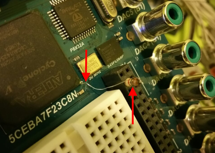
I managed to find a 1k resistor and I soldered a single strand of stranded wire onto it. I plugged the resistor into a nearby header and bent the wire strand so that it pushed against the A1 ball on the FPGA. This got the PLL's working.
We were about to run the -A9 boards on the pick and place tomorrow or Wednesday, but now we realize that we must rev the PCB first. There are also some benign VREF pins on the FPGA that will get grounded. Also, some pi filters will be made for the PLL power pins.
This a pain! These FPGA's are full of subtle gotcha's. When we got the -A7 board working, I tested out every connection to I/O's, but just assumed the PLL's would be fine, since their power was connected. Turns out on these Cyclone V devices there are more pins to mind than on earlier devices.
Anyway, this sets the -A9 boards back a few weeks and we need to figure out how to handle all your -A7 boards that have non-working PLL's. To make those boards work, two things can be done: solder a resistor and a wire together like I did, or just feed in a clock of the desired frequency into the SMA connector. Neither is pretty. For those of you with -A7 boards, we can make a clock generator that plugs onto the board somewhere and send you one, or we can offer you a new -A9 board for, say, $100. You can keep your old -A7. I don't know what else to propose. Is one better than the other?
Sorry about this pain in the rear.
Here is a picture of my resistor/wire fix:
I couldn't get the PLL's to work.
After trying everything I could think, it dawned on me that maybe there was some pin that we didn't connect properly on the FPGA. This happened initially with the VBAT pin and it prevented the FPGA from loading. It turns out that pin A1, which (very fortunately) is the ball closest to the corner indicator on the package, needs to be connected to a 2.0K resistor which goes to GND. It was not connected to anything on the -A7 board, as it was one of 8 pins we believed were optional no-connects. Google found me an Altera document that said otherwise today.
I managed to find a 1k resistor and I soldered a single strand of stranded wire onto it. I plugged the resistor into a nearby header and bent the wire strand so that it pushed against the A1 ball on the FPGA. This got the PLL's working.
We were about to run the -A9 boards on the pick and place tomorrow or Wednesday, but now we realize that we must rev the PCB first. There are also some benign VREF pins on the FPGA that will get grounded. Also, some pi filters will be made for the PLL power pins.
This a pain! These FPGA's are full of subtle gotcha's. When we got the -A7 board working, I tested out every connection to I/O's, but just assumed the PLL's would be fine, since their power was connected. Turns out on these Cyclone V devices there are more pins to mind than on earlier devices.
Anyway, this sets the -A9 boards back a few weeks and we need to figure out how to handle all your -A7 boards that have non-working PLL's. To make those boards work, two things can be done: solder a resistor and a wire together like I did, or just feed in a clock of the desired frequency into the SMA connector. Neither is pretty. For those of you with -A7 boards, we can make a clock generator that plugs onto the board somewhere and send you one, or we can offer you a new -A9 board for, say, $100. You can keep your old -A7. I don't know what else to propose. Is one better than the other?
Sorry about this pain in the rear.
Here is a picture of my resistor/wire fix:
Comments
A SMD resistor could be mounted one-end-up closer to the FPGA, and more 'bump-proof' ?
How similar will the FPGA PLLs be, to the final P2 PLLs ?
In another thread looking at FT600 parts, the P2 PLL-in would need to be 66MHz from FT600 CLKOUT (it uses a 30MHz Xtal), if they are to run in clock-synch mode.
Since you're revising now anyway, it might pay to get an A7 image (or p1v image) together so we can quickly test as much as we can and help prevent further revs
Did you get a chance to test the alternating video dac thing on the A9?
Also I'm about to get some pcbs made up on the local quickturn service. Can easily slip a 48 pin expansion board (simple breakout to DIL, for starters). But could add a Silabs clk generator easily too
I will get that -A7 imagine out soon. I can make it OR the PLL output ('0' when not working due to A1 floating) with some other pin, so you can get the clock in wherever you can.
We can't test the alternating DACs until the -A9 board is done. I've constrained I/O timing before on the Altera FPGA's, so I don't think it will be a problem. Until we get an -A9 committed to a PCB, we won't know, for sure. I'm pretty sure, though.
If you want to make some PCB's for the Prop 1-2-3, we do need some simple LED boards that we can plug into those five headers and monitor for simple visual patterns during production testing. We need a PCI-express board, too, with LEDs. We could get one of our guys to do it, but you are just as suited. We'd be happy to pay you for time and expenses, if you want to make them. It costs Parallax something like $75 an hour, burdened to employ an engineer. You might be similar, plus you already know exactly what to do. Either way, feel free. No expectations here.
There's only one PLL on the Prop2 and it multiplies the crystal by 1x/2x/3x/...16x for the system clock.
I think Altera's PLL's could be made to do something like that, but it would need their reconfigurable PLL which looks horrendously complicated to use for something so simple.
Does it make sense to fit an A9 to one of the PCBs you have, to check if anything else needs fixing ?
On a pre-reflowed board, you might be able to physically slip in a 0402 or 0603 resistor to reflow on the corner ball ?
Hmmm... Good idea. I've got to tell Ken that, because he was about to dismantle the pick-and-place setup tomorrow. I agree that we should make one, and try to address that A1 pin during production. Even if an 0402 was sticking out, we could later solder to it. I think that would be better than trying to connect it all at once. Thanks for pointing that out.
It looks trivial to modify what we already have for the 4 DAC R-2R resistor sets, just load leds and series resistors instead of 47 and 82 ohm R-2R resistors. Already have the stencil. Just need to replace trackwork and add a legend on the revised PCB, about an hours work, then do similar for the 48 pin and 3 expansion ports
There wouldn't be a charge, we'd swap you for an A7 image : )
How many sets did you want?
We'd need two boards for the 32-I/O headers and three boards for the Exp A/B/C headers which are 8 I/O's each. And then maybe a few extras in case we broke something.
We are happy to pay you materials and time, and give you FPGA images. Or, maybe you'd like a shiny new -A9 board with real video DACs that can be dithered nicely.
Luckily, there aren't many A7's out in the wild (unluckily, I have one). I'm still trying to digest the alternatives to fix the problem as I soak up my morning coffee. The whisker wire seems a bit unreliable as a realistic solution.
Just another opportunity to make lemonade on the journey to P2! :0)
- PCB revisions made between 9-15 and 9-22.
- PCB files ordered 9-24 (quote takes a day or two)
- PCBs arrive at Parallax 10-14
- Pick-and-Place 10-14 to 10-30
We can't provide a better estimate on the PnP because other regularly scheduled production jobs will be on the line, so these will need to fit in between them, requiring a few days of leeway.
My estimate is about six weeks until we have the revised -A9 boards in our hands, around November 1st.
We'll do whatever we can to speed this up. And believe me, I want it completed more badly than anybody can imagine.
Ken Gracey
I imagine it'd be devastating to do the production run and then find a fatal flaw...
Out of curiosity, did you do the bga board with a through hole under every ball?
I've heard of people doing it that way.
If so, maybe there's an SMT fix possible on the backside?
BTW: I'm definitely in for one of the -A9 boards when they are ready.
BTW2: I've begun to realize that the more complex you PCB gets, the more things that need to be tested to make sure they work... Testing starts to take as much time as assembly... PC board makers must have some kind of automated testing setup...
By default, my 123A7 board operates a little differently to Oz's, and looked to have the same problem Rjo's 2 boards showed.
It seems doing chip's operation of pushing 1 kohmed ground wire under ball A1 makes everything work, including the ws2812b leds, which are timing sensitive. Furthermore things continue to work for at least several seconds after removal of the PLL pull down, but after that few seconds you can see the timing go erratic, and the ws2812b's go flaky.
With such a high impedance, that time constant is probably dependent on surface wash residue etc, which would explain why it can go either way. I'm guessing some 123A7's naturally pull down, but most probably pull up, due to more vcc than gnd pins in the area.
Good to progress the understanding of what's going on. And good work putting the flaky pin in the corner rather than other 480 harder to get to pins!!
Edit: 3 neighbors are gnd, there goes that theory. Perhaps pin A1 is influenced by the plane immediately below top layer, or the nConfig track running past
Nice sniffing!!!
That explains why sometimes, a restart ends up with a variable amount of time before my P1V's Cog0 LED comes on.... and why at times, I think it is dead and at other times I am delighted to run my Spin programs:)
Here's a good one:
The below snippet works every time using a real P1....Propeller Activity Board, PropBOE, etc.
But the P1V version only works by reloading the code to RAM...
the fpga board doesn't matter... DE2-115, P123,BeMicro(s).
Let me say that again.... the first time I run a program, it may work. If I reload the program to ram and it worked the first time... it doesn't work on the reload, but if it didn't work the first time, then it does work on the reload.... every other time it (that is on odd numbered reloads) it doesn't work... all day long. Really odd.
The nearly identical Pasm version, which I run after it and before it works every time... putting it in a repeat loop has no effect on this behavior... It is as though there is a bit set and reset in the P1V itself by the act of loading to ram. I have no idea whether it is counter b or the waitpeq/waitpne that is at fault. Again... this is only a problem in SPIN. PASM is just fine.
Proptool/PropellerIDE same behavior.
code]
pinstate:=1<< _CAM_VSYNC_PIN
ctrb := %01010<< 26 + _CAM_HREF_PIN
frqb:=1
waitpeq (pinstate,pinstate,0) 'wait til vsync hi
waitpne(pinstate,pinstate,0) 'wait til vsync low
phsb := 0 'start measuring positive edges on HREF
waitpeq (pinstate,pinstate,0) [/code]
Rich
What I didn't mention above is you can then put the pull down back on and everything is instantly good again. That makes me hopeful that even intermittent kludge connections, as long as they don't break contact for more than a few seconds, still have a good chance of working
I've managed to (deliberately) jam a 0603 1k5 resistor under the corner on a 45 degree angle, half in and half sticking out. Touching the exposed end to gnd fixes things, so next step is to solder it in
Wow! Sounds like what we need to be doing, too. So, there's clearance for an 0603? Maybe an 0402 could go right between the A1 ball and a GND. Getting heat in there to solder seems really tricky. If you could get it to work, though, it would be a very robust fix. No danger of it getting rubbed out, as it would be very secure. That resistor is supposed to be a 2.0k 1% tolerance part. 1k is close enough for us, though.
I think what might work is
- scrape off some solder resist near the fpga orientation dot, exposing gnd
- tin one end of an 0603 2k 1%
- file it so its solder has the original 0603 height
- push it under on a 45 degree angle as far as it will go against the a1 ball
- heat the other end of the 0603 with an iron, conducting heat through the 2k to melt into the a1 ball, while applying gentle pressure to maybe slide it
- terminate the other end of the 0603 to the scratched off solder resist
Here's a halfway photo of the wedged 1k5 0603. Touching the (pulldown+1k) to its end restores order
The 1k5 is just what we have on hand. Can get 2k 1% in of course. Perhaps get several brands and use the lowest height
Materials...
1) Resistor 2K 1% 1/10W or 1/8W (very small style - lead needs to be small enough to slide between the FPGA and PCB)
2) Thin solder/flux
3) Optional heatshrink/spaghetti to slide over resistor
Instructions...
1) Trim one resistor lead to ~1/2" and tin this lead
2) Poke this resistor lead under the FPGA until it touches the ball
3) Heat this lead (closest to the resistor) with the soldering iron until it gets hot enough to solder to the ball.
4) Optionally slide the heatshrink/spaghetti over the resistor and leads, leaving a small part of the unsoldered resistor lead exposed
5) Solder the exposed resistor lead to a ground point on the PCB
The RBF image and SPIN code are the one's I posted in
this thread here
Strangely on my board it loads/runs P1V code first time every time and PropTool detects a P1 without fail.
Even serial comms shows stable results compared to the results on Tubular's board.
Same code, two entirely different results. I must be the "lucky" one with a naturally stronger pull down than you guys.
Maybe I need to change my middle name to "Theremin" and/or rename my workshop "Faradays Place"
Anyhow the PLL issue seems to be the answer to "all" the A7 board weird stuff.
P2 here we come.......
Time to poke my a1 ball!!
I also bought in a range on 2k 1% resistors overnight. The Bourns ones had the lowest profile of the 4 brands. The 1/8 watt resistor is around the same height, but has the advantage of being malleable (hammer it) if required, but the 0603s should end up much neater.
e14 part# Newark# Mfr Part# thickness mm
1/8 watt ? ? ? 0.453
1469764 ? Vishay CRCW06032K00FKEA 0.443
1811635 ? Koa Spear RK73H1JTTD2001F 0.445
2008337 32k2272 Bourns CR0603-FX-2001ELF 0.434
1894123 ? Panasonic ERJP03F2001V 0.468
I'm looking forward to seeing what you come up with!
For those with Prop123 boards who can't make this fix, I can just make a straight 50MHz image that uses the on-board 50MHz directly, circumventing this PLL issue.
As long as he doesn't start posting pictures.
So far, no joy when poking and prodding with the lead of a 2K 1/8W resistor under the little arrow on the FPGA. I assume my a1 ball is right under there. The other end of the resistor is grounded, of course. The lead appears to be small enough to fit under the chip. I guess I could make a teeny-tiny whisker wire and try that. It's safe to say we have exceeded the capacity of my eyes to focus on tiny with this adventure!
The test program continues to run but no change in the pattern on the ws2812.
I recall some comments about the WS2812s possibly not being good on these boards - didn't survive the baking process. Is there a better test for proper PLL operation that doesn't rely on the WS2812s?
As an alternative, I think I'll order a PLL module from Adafruit and see how that works.
Re: Si5351 breakout solution - that's a really nice I2C programmable clock chip. I've ordered the board and connectors. Being a programmable clock, it needs something to talk to so you can set it up and get it running at the speed you need. It looks like I'll need to build a little "clock box" for my bench out of the breakout board and a spare Arduino (quickest solution since Adafruit has a sketch already).
I also found SMA cables on Ebay (US + free shipping)
So, I'll be able to try an external clock solution some time next week.
I have had a related problem in my working on FPGA code, a floating CTS line that requires a pull-up resistor.
What I did discover is that it is possible to configure pull-up or pull-down resistors on the i/o internally in Verilog or VHDL. The only thing I am unsure about is that you can get the 2K ohm value that you desire.
If you can just configure the i/o as a pull-down, why bother with all the problems of a hardware modification?
That's why we need to go poking with wires!!!
Maybe use some flat pliers to squish the end of that resistor lead so that it is adequately thin. I had to go to really thin wire to get under there.
It seems a flattened copper wire would be best for a soldering attempt, as the copper is going to conduct heat the best. Plus, if the wire is flattened, it has more cross-sectional area than a similarly-thick round wire and so it will carry heat to the ball better.
Guys, the best solution to this problem, if you can do it, is to get that A1 ball connected to a 2k resistor to ground. It means no extra parts and your Prop123 remains monolithic.
Can anyone else find it?