

Propeller ADC Calculations
 Cluso99
Posts: 18,069
Cluso99
Posts: 18,069
I will be using a Propeller to monitor the voltage on a 24V Lithium Battery Bank. I want to monitor each cell in the bank as well as a shunt to measure current (either charging or discharging).
There are 8 cells in a 24V bank.
Here is my circuit (taken from Parallax's ADC Sigma-Delta App Note). I am using multiple copies of this circuit.
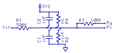

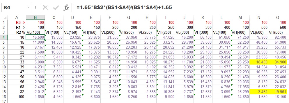
Here are the data calculations. Note the formula shown for the Low Voltage value. The High Voltage formula has "+" instead of "-".


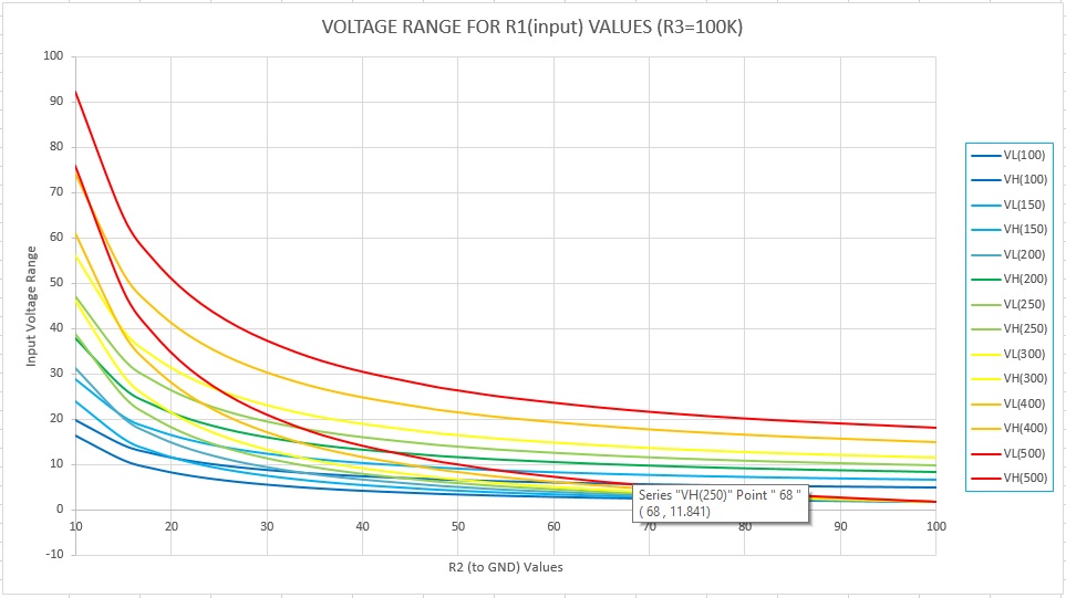
And here is a graph of those values/ranges.

Here is the spreadsheet (you will have to remove the ".txt" extension)
Propeller_ADC_Calculations.xlsx.txt
Now for some explanations...
Each battery cell is ~3.2V. To keep it simple, let's assume it is 3V.
Therefore I need to read values around 0V, 3V, 6V, 9V, 12V, 15V, 18V, 21V, 24V. I will require 8 ADC circuits for this.
Typically the feedback resistor (from the prop pin) R3=100K.
As seen from the data calculations, I get a bigger range if I use an input resistor R1=500K.
R2=150K gives a range of -1.100V to 15.400V
R2=56K gives a range of 8.132V to 24.632V
R2=33K gives a range of 18.400V to 34.900V
So, with just 3 variations, I can read my 8 cells.
However, if the voltage drops dramatically overall, I will not be able to read the overall voltage. So I am going to add a 9th ADC circuit to also read the 24V value.
This time, R1=500K, R2=56K and R3=47K. This gives a range of -1.171V to 33.935V.
For the shunt (in the -ve lead from the battery to ground), I need to read a value between +/-150mV and 0V.
R1=33K, R4=33K, R3=100K gives a range of -0.5V to +0.5V (note the use of R4 and not R2).
There are 8 cells in a 24V bank.
Here is my circuit (taken from Parallax's ADC Sigma-Delta App Note). I am using multiple copies of this circuit.
Here are the data calculations. Note the formula shown for the Low Voltage value. The High Voltage formula has "+" instead of "-".
And here is a graph of those values/ranges.
Here is the spreadsheet (you will have to remove the ".txt" extension)
Propeller_ADC_Calculations.xlsx.txt
Now for some explanations...
Each battery cell is ~3.2V. To keep it simple, let's assume it is 3V.
Therefore I need to read values around 0V, 3V, 6V, 9V, 12V, 15V, 18V, 21V, 24V. I will require 8 ADC circuits for this.
Typically the feedback resistor (from the prop pin) R3=100K.
As seen from the data calculations, I get a bigger range if I use an input resistor R1=500K.
R2=150K gives a range of -1.100V to 15.400V
R2=56K gives a range of 8.132V to 24.632V
R2=33K gives a range of 18.400V to 34.900V
So, with just 3 variations, I can read my 8 cells.
However, if the voltage drops dramatically overall, I will not be able to read the overall voltage. So I am going to add a 9th ADC circuit to also read the 24V value.
This time, R1=500K, R2=56K and R3=47K. This gives a range of -1.171V to 33.935V.
For the shunt (in the -ve lead from the battery to ground), I need to read a value between +/-150mV and 0V.
R1=33K, R4=33K, R3=100K gives a range of -0.5V to +0.5V (note the use of R4 and not R2).

400 x 186 - 20K
993 x 354 - 185K

963 x 541 - 107K

Comments
Regards
Bob
Why use an external ADC chip? The prop is quite capable on its own. An external chip still requires 2 resistors as a voltage divider, and caps to stabilise are a good idea. That only leaves the feedback resistor(s) that can be saved vs a dedicated chip. Plus I would require 2 ADC chips since I need 9 channels.
I have laid out a pcb with 12 channels (wip). Currently I am not sure about what else to include... MicroSD, LCD, LEDs plus an external interface (serial ?), push buttons or a rotary/switch.
evanh, I need to google bottom balancing. I am using a smart charger, but I want to ensure a cell doesn't fail.
Mainly wanted to mark this thread with my input so I can find it easier later on. Thanks for sharing!!
A simple go/no-go you can probably get, but differential cell voltages are going to be harder to get precision on.
Especially across a divider ratio change, so I would add more channels so you can avoid trying to measure a cell difference across a divider ratio.
Better may be to use analog muxes into a single differential ADC.
The first ADC circuit connects to the shunt (-ve battery). This measures the current in/out of the battery. It's range is +/-0.5V.
Then each battery cell is connected to each of 8 ADC circuits. So, I am measuring successive voltages, and need to subtract the previous voltage to obtain the actual cell voltage.
It is a monitoring circuit to advise the user if something is wrong (cells are out of balance) and to trip a contactor to remove the charger/battery to prevent damage.
I see no need to complicate matters by adding lots of extra circuitry.