

Testing with DE0-Nano without adapter board
 mindrobots
Posts: 6,506
mindrobots
Posts: 6,506
I'm giving up my Nano Adapter board for P2 Emulation testing.
How to connect serial I/O:
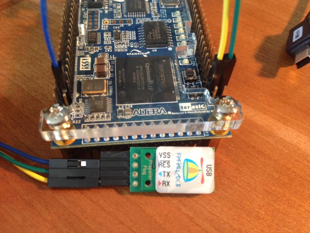
Yellow - PropPlug RCV -> Nano TX
Green - PropPlug TX -> Nano RCV
Blue - PropPlug RES -> Nano RESn
(not shown) - PropPlug VSS -> Nano VSS
With the Nano placed so Altera and DE0-Nano text is right side up (the Nano USB will be at upper right corner)
VSS is on left hand pins, outside row, 6th pin from the bottom (one of many VSS)
RESn is on left hand pins, inside row, second pin from bottom.
Nano TX is on right hand pins, inside row, second pin from bottom
Nano RCV(RX) is on right hand pins, outside row, second pin from bottom
This gives you serial I/O through the PropPlug.
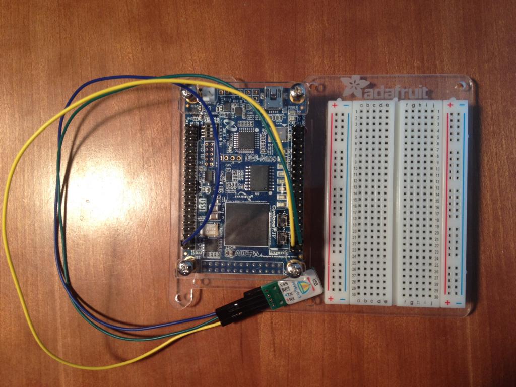
Bonus, Adafruit makes a Proto Plate for the Beagle Bone that works as a nice little "proto Plate" for the Nano. Two of the holes line up so you can attach it firmly and then put a half sized bread board (400 pin?) I need to try one of PropellerPowered "sleds" to see if they fit - the Nano is ALMOST the same size and hole arrangement as the QuickStart.
And Pnut works fine running under Win7 on a Mac running Parallels. Yay!
I plan to post here any aids for folks testing the P2 using the Nano without an adapter card.
Feel free to contribute if you have anything to add.
How to connect serial I/O:
Yellow - PropPlug RCV -> Nano TX
Green - PropPlug TX -> Nano RCV
Blue - PropPlug RES -> Nano RESn
(not shown) - PropPlug VSS -> Nano VSS
With the Nano placed so Altera and DE0-Nano text is right side up (the Nano USB will be at upper right corner)
VSS is on left hand pins, outside row, 6th pin from the bottom (one of many VSS)
RESn is on left hand pins, inside row, second pin from bottom.
Nano TX is on right hand pins, inside row, second pin from bottom
Nano RCV(RX) is on right hand pins, outside row, second pin from bottom
This gives you serial I/O through the PropPlug.
Bonus, Adafruit makes a Proto Plate for the Beagle Bone that works as a nice little "proto Plate" for the Nano. Two of the holes line up so you can attach it firmly and then put a half sized bread board (400 pin?) I need to try one of PropellerPowered "sleds" to see if they fit - the Nano is ALMOST the same size and hole arrangement as the QuickStart.
And Pnut works fine running under Win7 on a Mac running Parallels. Yay!
I plan to post here any aids for folks testing the P2 using the Nano without an adapter card.
Feel free to contribute if you have anything to add.

1024 x 768 - 113K

1024 x 768 - 122K
Comments
SORRY, THIS WAS NOT CORRECT. IT SHOULD BE DELETED IF YOU"VE SAVE A COPY!
Thanks! I can do that. None of the other references to hooking this up said it was required but I got wire, so I can do it!
(If I can find a Nano pin that has VSS :frown:)
http://forums.parallax.com/showthread.php/153422-HUB-EXEC-Update-Here?p=1238040#post1238040
C.W.
Here's the i/o pinout map. This is from the point of view of the mating female connector. The USB is up the "NC" end of the connector
The other header breaks out the 4 channels of 9 resistors. I'll post that later with shots of what the pcb looks like.
I can probably make the resistive breakouts available (assembled) too if this helps, it would be easy to lop off an existing design.
The NC's are not to be connected (input only on the Altera chip so not useful for gpio). The B0L and B1 are the LSB's of one of the dacs, otherwise all the dac pins come from the other header.