

Can I use Zener diode to boost up LDO Voltage ?
 john_s
Posts: 369
john_s
Posts: 369
Let's say I have a 1.5V LDO and would like to have it working as a 5V regulator - can I simply place a 3.5V Zener diode in its GND leg?
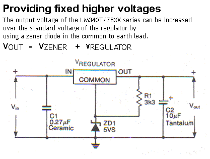
I've never tried it but according to some app notes it's doable with 78XX series etc.
Does the same method apply to modern LDO voltage regulators?
What are the negative aspects of such approach?
I've never tried it but according to some app notes it's doable with 78XX series etc.
Does the same method apply to modern LDO voltage regulators?
What are the negative aspects of such approach?

417 x 315 - 29K
Comments
However, you might want to add a small capacitor, 0.1uF to 1uF, across the zener to improve the transient response.
Duane J
-Phil
You might be better off with a blue LED in the ground leg. At those voltages, LEDs have sharper knees than zeners.
Thank you all - I appreciate your comments especially in regards to swinging LDO ground leg and stability...
I sensed that there's more behind it then just adding a Zener
Erlend
However, the zener voltage can be quite stable when used in this application as the current through the zener is essentially regulated.
1. The quiescent current coming out of the ground pin of most regulators is fairly stable.
Quiescent current for the LM340-x1 or LM78xx series is 6mA max and a change of current of about 0.5mA.
2. The current through R1 is highly regulated by the constant voltage of the regulator itself.
Common low wattage zeners such as the 1N52xxB operates best at a zener current of about 20mA.
Calculate R1 for a 10V output:
LM7805 5 volt regulator
IQ = 5mA quiescent current @25C (as in the chart)
1N5231B 5.1V .5W zener
IZT = 20mA test current
R1= 5Vreg / (20mAIZT - 5mAIQ) = 333Ω
330Ω would be the closest standard value.
5Vreg2 / 330Ω = .075W of power dissipated in the resistor.
5.1Vreg * 20mAIZT = 0.1W of power dissipated in the zener.
Duane J
Tracy's point, however, is that this is not the case with LDOs, where the quiescent current is roughly proportional to the load current.
-Phil
It can work very well indeed if a synthesized zener such as the LM385 is used in place of a regular zener. The LM385 has a sharp knee and constant voltage for currents from 20µA to 20mA. If you don't happen to have LM385s lying around, though, it's better to buy the voltage you need.
I was referring to LDO regulators that employ a collector-loaded (PNP) pass transistor. Here is a diagram of ground pin current vs load current, the graph on the left. The graph on the right is ground pin current vs input voltage at several different load currents. This is for an LT1963-1.5, which happens to be both low dropout (LDO) and also low power. The low power refers to the point that the ground pin current drops to about 1mA when the output current is zero.
In contrast, here is the ground pin current of an LM2940, which is LDO but definitely not low power:
Even at no load, it sucks over 10mA of quiescent current, and that doubles as it goes toward full load at 1A.
A regulator such as the MCP1703 has a p-mosfet output, and the drive requirements are considerably less, still proportional, but measured in microamps. This qualifies as micro-power, because the ground pin current at zero load is a mere 3µA.
A non-LDO, emitter -loaded regulator like the one in the 78xx series does not have much change in ground pin current as the load varies. The current to drive the output stage flows into the load instead of being lost out the ground pin.
@ Erco & all, happy holidays indeed. It is truly a pleasure to read here and to participate in this community.