Shop OBEX P1 Docs P2 Docs Learn Events
Tachometer resolution — Parallax Forums

Tachometer resolution

Scott4Scott4 Posts: 45
edited 2011-10-19 09:36 in BASIC Stamp
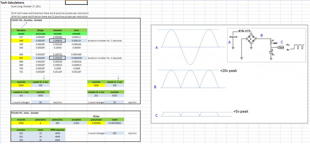
I want to embed a tachometer in my project and I am bumping up against an issue of resolution. I have a Rotax engine that has 12 poles on the flywheel alternator. The tach wire generates an AC signal with 6 cycles per revolution.

The attached spreadsheet (image) shows that if I use "COUNT" with 12 pulses per revolution and wait around for 0.2 seconds, the resolution is 25 rpm. Waiting around and counting for >0.2 seconds is not acceptable as I have lots of other tasks for my BS2px to do.

If I use "PULSIN" with 6 pulses per revolution I can only get a resolution of 202 rpm.


Anyone have a solution to get better resolution? Thanks for the help. -Scott
1024 x 476 - 69K

Comments

  • ercoerco Posts: 20,254
    edited 2011-10-18 14:37
    You need more pulses per revolution. Got any room on an exposed rotating shaft to wrap around? PhiPi had an ingenious application for fridge magnet/hall effect encoder here: http://forums.parallax.com/showthread.php?130799-Refrigerator-Magnet-Encoder&highlight=encoder
  • Scott4Scott4 Posts: 45
    edited 2011-10-19 07:51
    Thanks! That is ingenious. I knew about the selective magnetization of elastomeric magnets but never imagined using them for an encoder in this fashion. I wanted to use the tach wire because it's EASY but may have to see if there is a way to get to the shaft. Thanks again for the help. -Scott
  • ercoerco Posts: 20,254
    edited 2011-10-19 09:36
    Also, if you can mount 2 hall effect sensors around your flywheel alternator, you can make a quadrature encoder which would double your existing resolution.
  • A fully digital car tachometer IS possible with a Basic Stamp 2sx chip. I built one that is not only fast, but it also runs the speedometer. These two instruments in any car need to be extremely responsive. That is why you need to dedicate one chip to display just the functions that require a high response time (this excludes things like oil pressure, fuel level, voltage and temperature which are a piece of cake with the RCTIME function). To effectively make this happen, you need to use the PULSIN function (not COUNT). Trust me, I really tried to make it work with COUNT, but the response just was not fast enough. The one I built is tied into an LS1 engine in a Camaro that I race and it's dead accurate. A couple things required to make this work is a good understanding of the integer math that limits Basic Stamps (but also makes them fast). Calculating the frequency requires an equation that generates the Period based on inputs from the PULSIN function. Then some interesting synthetic division (to get the accuracy required) in order to calculate the frequency and finally the RPM or Speed (all these calculations may sound like a lot, but the SX chews them up pretty fast). I also added a rate change filter algorithm to limit spikes. The calculated values get fired out in serial form to a MAX7219 chip for a combination 4 digit seven segment LED display and 32 individual LED's to form a bar graph. The entire process is wrapped up in one DO Loop. Anyone interested, let me know, I've already been through the pain of multiple paths down the wrong road on this project and I'm finally happy with how it turned out. Just don't attempt it without using an SX or better (you need the speed of the faster stamps).
  • truetech wrote: »
    A fully digital car tachometer IS possible with a Basic Stamp 2sx chip. I built one that is not only fast, but it also runs the speedometer. These two instruments in any car need to be extremely responsive. That is why you need to dedicate one chip to display just the functions that require a high response time (this excludes things like oil pressure, fuel level, voltage and temperature which are a piece of cake with the RCTIME function). To effectively make this happen, you need to use the PULSIN function (not COUNT). Trust me, I really tried to make it work with COUNT, but the response just was not fast enough. The one I built is tied into an LS1 engine in a Camaro that I race and it's dead accurate. A couple things required to make this work is a good understanding of the integer math that limits Basic Stamps (but also makes them fast). Calculating the frequency requires an equation that generates the Period based on inputs from the PULSIN function. Then some interesting synthetic division (to get the accuracy required) in order to calculate the frequency and finally the RPM or Speed (all these calculations may sound like a lot, but the SX chews them up pretty fast). I also added a rate change filter algorithm to limit spikes. The calculated values get fired out in serial form to a MAX7219 chip for a combination 4 digit seven segment LED display and 32 individual LED's to form a bar graph. The entire process is wrapped up in one DO Loop. Anyone interested, let me know, I've already been through the pain of multiple paths down the wrong road on this project and I'm finally happy with how it turned out. Just don't attempt it without using an SX or better (you need the speed of the faster stamps).

    Welcome to the forums! You have responded to two posts that were 5 years and 12 years old.

    Sounds like the SX did everything you wanted. Would you like to share your code so others can benefit from it?

  • ercoerco Posts: 20,254
    Welcome to the forums, truetech!
Sign In or Register to comment.