

Switch-mode power supplies
 Peter Jakacki
Posts: 10,193
Peter Jakacki
Posts: 10,193
Although this is not Propeller specific nonetheless the post is directed to fellow Prop'ers where frequently discussions about power supplies pops up. A lot of members just use linear regulators because they are nice and easy whereas switchers sound too complicated. Then when someone does use a switcher they end up with a big TO220 pack device and big caps etc (ugly).
The point of this post is to highlight how simple a switcher can be and just how compact too. Have a look at this small module (it's one of mine), it measures just 0.78" x 0.45" with an overall depth of 0.3" because of the inductor on the reverse side.
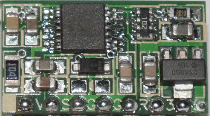
The 7 pins are 0.1" spaced and allow for on/off control and adjustment of the regulation voltage which is normally set to 5V. There's also a 3.3V LDO regulator onboard that doesn't break a sweat or even get warm even at 250ma load. As you can see there are no big electrolytic or tantalum capacitors in sight, just cheap ceramics. It's based around a LM5010A which can operate at up to 1MHz switching frequency and up to 75V voltage input. The standard components that I use on this will allow it to operate up to 50V as is. Total cost of parts per module is less than $4 but it means a small footprint, high input voltages and output currents up to 1A.
OK, that's my design tip for the day.
The point of this post is to highlight how simple a switcher can be and just how compact too. Have a look at this small module (it's one of mine), it measures just 0.78" x 0.45" with an overall depth of 0.3" because of the inductor on the reverse side.
The 7 pins are 0.1" spaced and allow for on/off control and adjustment of the regulation voltage which is normally set to 5V. There's also a 3.3V LDO regulator onboard that doesn't break a sweat or even get warm even at 250ma load. As you can see there are no big electrolytic or tantalum capacitors in sight, just cheap ceramics. It's based around a LM5010A which can operate at up to 1MHz switching frequency and up to 75V voltage input. The standard components that I use on this will allow it to operate up to 50V as is. Total cost of parts per module is less than $4 but it means a small footprint, high input voltages and output currents up to 1A.
OK, that's my design tip for the day.

800 x 445 - 96K
Comments
In comparison to a linear regulator it covers the same area as a 7805T (without heatsink) in a TO220 pack when you lay them both flat. For a test I hooked up a 7805T without a heatsink to the same 500ma test load and by the time I had cranked the input supply up to 9V the regulator was running that hot I couldn't touch it. To dissipate that kind of heat needs a good heatsink and good ventilation assuming that the ambient temperature is being kind which is not always the case. I would not try running the 7805 at voltages much higher than 12V then and definitely not at 24V (even much less 48V). At 24V the 7805 would be "trying" to dissipate 9.5W and that kind of heat would burn the PCB it's on unless you had a huge slab of metal to spread it. The thermal resistance to air of a 7805T is 65'C/W!!!
The little 5010 switcher doesn't even feel like it's turned on as it's running just as cool as if it's off.
So a linear regulator might be rated for 1A but doesn't mean you can get it easily if at all.
Perhaps the way out of this would for me to boost 3.X V up to 5.0 V and then drop it back down again (5 V is always useful). This route would still be smaller and certainly more efficient than two Li cells and my usual twin regulation down.
Very nice project! What are you going to do with this?
Bruce
This is just a general-purpose switcher module that I use in a lot of my designs. It is footprint compatible with and replaces an earlier generation of switchers that ran at lower switching frequency with larger caps etc. I will probably look at getting these made up externally in some volume if the price is right etc. At the moment they are for internal use but if I do get them manufactured in volume then I could make them available. Even so I could probably make a small quantity available for now at a reasonable price (but not $4).
BTW, I could design a switcher straight onto the target PCB but this module fits into tight spaces and also makes it easier on the PCB layout etc.
I've been using switchers for several years now and your design is a quantum leap in terms of size. Do you have a parts list?
You can check out a design on national semi's website www.national.com and create a login then go to webench where you can test your design and it does all the sims and boms etc. A very powerful tool but you have to do your own pcb, it won't do that for you
I used it's values as a basis for my design but I didn't follow it verbatim. The design worked first time, even when I (after donning safety goggles) cranked up the input voltage and loaded it right up, no magic smoke!
I had done my research and had missed this ic. I just happened to chat to Peter on the very day I was finalising my research and was going with a different part. Timing was perfect, and I am going to use Peters modules (and my pcb has been changed to take it). Sometimes little modules that can be built in bulk and plug into other pcbs work out cheaper in the long run.
I presume it is a lower uH value than the simple switchers, but it still would need at least 1A current rating?
This part is 68uH and the reason for this is to do with the wide supply range I am looking at. The part costs me 28c each in 100 quantities from Digikey. Saturation current is 1.3A max which is fine for practically all my needs.
Also the module is designed with a dual footprint so I can spec a different inductor if need be,
That layout is a work of art -- not just engineering! there's not a square micrometer of wasted space!
-Phil
And a damn fine tip of the day it is
Thanks again!!!
Frank Freedman
If you did do that, would you consider a 3.3V version and a 5V version?
Hi Drac, one of the reasons I switch to 5V first and then 3.3V is to get a cleaner logic supply especially for analog functions, that's why there's an LDO on the module. Anyway, there's a pin available where you can just add your own adjustment resistor to take the voltage up or down to suit.
that's what I was hoping to hear. Looking forward finding the price and availability.
However, this pcb module is ideal to power a prop and is simple to wire it up.
You have been kind enough to help me in the past and I am wondering if you would be willing to provide me with a little more guidance.
I want to design a new stepper driver with a Propeller on board, that can operate over a wide voltage range. My thoughts are to feed the input voltage into a LM5010A and the output voltage of the LM5010A into a LM2937-3.3 for powering the Propeller chip, meanwhile also bypassing the LM5010A with the input voltage to feed the DRV8825 stepper driver.
My question is this:
In section 8.2 Typical Application, of the LM5010A datasheet, an example circuit is shown with an input voltage ranging 6-60V, with an output voltage of 5V. Can this example circuit be used "as is" to feed a LM2937-3.3 regulator for reliably powering a Propeller?
As always, any effort that you may put forth into answering this question will be greatly appreciated.
Bruce
Input voltage 7-36Volt max 1,5A exist in 3.3 and 5Volt 85% efficiency.
We use them on a motorbikes with huge HF transmitters 3-7GHz
We just put capa's in front and after
Daniel
For sure those regulators are great off-the-shelf components as are the Recom R-78 series too but they don't come close to the 70V max input rating of the LM5010A which I use in some designs since I made my own tiny modules for these. I'm wary of just sticking any kind of cap on the output though, I may use a 10uF tantalum but I wouldn't load them up too much whereas the input cap is typically a 100uF electro fed from a diode and a series "fuse" resistor. However at the higher input voltages it's easier to use ceramic caps. For that extra bit of input voltage reach I sometimes even use a series zener to drop the voltage a bit more since the input current at that voltage is much lower.
Thank you for your response and input.
The Evaluation Board for the LM5010A has a very similar schematic and the App Note(AN-1423) contains a bill of materials. My thoughts are to order the exact same parts as used in the Evaluation Board, or equivalents. For the Evaluation Board they list this inductor: http://www.mouser.com/ProductDetail/TDK/SLF12575T-101M1R9-PF/?qs=VpQJLEvtbIYoNWgTZeTebQ== I am hoping this will be Propeller friendly.
Of course a "LED power indicator" is a must for the type of board I intend to fabricate and the 5V rail is a good location for this LED as you indicate, which does take care of the minimum 500ua load, but doesn't R1 and R2 of that schematic take care of that minimum load?
It is not necessary to answer that last question, because I will of course be adding the LED as suggested.
I will definitely take a look at the MCP1700.
Thank you for your input Peter. As always you have been very informative and helpful. I hope all is well with you and your family. Good luck with Tachyon V4.... I have been following along with the thread for a while now... Sounds like you have made quite a bit of progress.
And most importantly, have a very Merry Christmas Peter!
http://www.mouser.com/Power/DC-DC-Converters/Non-Isolated-DC-DC-Converters/_/N-brvxxZscv7?P=1yxt7boZ1yxt79hZ1yxt79nZ1yxt79pZ1yxt7bdZ1yxt6o1Z1yxt77oZ1yxt7adZ1yxt7a4&Ns=Pricing|0
Interesting link... nice to know that stuff is available.
Okay... So what is the benefit to buying a module, besides drawing it all up and the soldering?
The downside would be the voltage limitations for several of the products.
I just got finished creating the devices for the DRV8825 and the LM5010A in Eagle. After placing those devices into a board, I did a print out and wow those devices are small.
How expensive is it for a board house to place and solder devices? I realize that is a difficult question to answer, so I am looking for either an "OUTRAGEOUS" or "reasonably priced".
For 0.65mm pitch items get oshstencils.com and you should be able to do a few boards by hand.
Integrated Current Sense keeps steppers happy.
http://www.ti.com/lit/ds/symlink/drv8885.pdf
This simple-switcher have Integrated Synchronous Rectification (saves your from getting a diode) and large 1.27mm pitch
http://www.ti.com/lit/ds/symlink/lmr23610-q1.pdf
Get a Stepper driver that is SOIC too, for example:
http://www.mouser.com/ProductDetail/Texas-Instruments/DRV8803DWR/?qs=sGAEpiMZZMvS/YaWaOF378TkULp/Z%2bZz
By only using SOIC 1.27mm pitch with 0805 caps and resistors, easy stuff to do by hand.
Instead of hijacking Peter's thread and going way off subject, I would be more than happy to discuss all of these issues within the thread I started for the stepper driver, which can be found here: forums.parallax.com/discussion/165669/eagle-complex-device-and-vias-stepper-driver-discussion