

Hints About My New Project (Video)

Last weekend I started working on a new robotics project. I wanted to branch out with this project, so I'm going to use metal and use the Propeller chip to control it. Now it's been years since metal shop, but I do remember that while aluminum is light and strong, it is nearly impossible to braze. Brass on the other hand is softer and heavier, but easier to work with. As this project will be fairly small, it should be strong enough. Brazing can be tricky as brass anneals quickly at that temperature, but brass silver solders like a champ.
So over the weekend I got some brass and made one of the first parts to my new project:
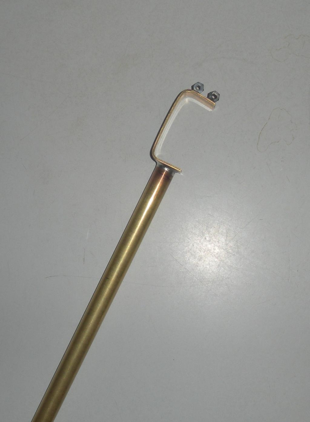
Can you figure out what the rest of it will be? More hints.
I've learned a little Spin and it looks OK. I've also learned how to poke around the object exchange for code. I'm going to need a servo controller object. Any one considered the best?
Now I already have code to do what I want in C/C++, so Catalina might be easier than porting the code. But will I lose access to the Spin servo controller?
So over the weekend I got some brass and made one of the first parts to my new project:
Can you figure out what the rest of it will be? More hints.
I've learned a little Spin and it looks OK. I've also learned how to poke around the object exchange for code. I'm going to need a servo controller object. Any one considered the best?
Now I already have code to do what I want in C/C++, so Catalina might be easier than porting the code. But will I lose access to the Spin servo controller?

1024 x 1394 - 83K
Comments
Kye's Dual Servo driver is a very straightforward and easy to use object for one or two servos. Otherwise, Beau's Servo32 object is pretty universal.
Thanks for the pointer to Beau's Servo32 object as I will be controlling more than two servos.
-Phil
@Phil, it could work as part of a spider robot leg, but that's not what I'm building. Thanks for the compliment, but you don't want to see my attempt to braze brass! I also learned that brass doesn't harden when you quench it.
@P!-Ro, I'm hoping funny looking won't describe it when I am done. But you're the closest. It's the ulna and elbow joint for a robot arm. I haven't yet used the pipe cutter to cut the ulna to length as I need to build the wrist servo holder first.
I found some C code to do an inverse kinematic transform, I ported it to C# and commented it so I would understand it. Now I need to learn how to do integer or fixed point trig in Spin to port the code.
Sorry.
Can you guess which part of the flux capacitor this is?
Okay, perhaps that wasn't too great of advice.
Erco, lol!
Whit, given how much work one robot is, an army is out of the question.
Not if you build a self replicating robot with it's first task as making 2 replicas.
Here it is attached to the servos, the humerus, and the base:
I started with the humerus and thought of using silver solder with tubing after I built it. I used that for the ulna and liked the way it came out, so I may build a new humerus using that technique. But I'm going to resist this until I get it working. You may have seen me post some floating point code in the Propeller forum. That's part of an inverse kinematic program I found in C that I gave up trying to port to PBasic. But Spin and the Propeller look like they can handle it.
Any details on the soldering technique you used?
How did You apply the heat to the brass and silver?
Was super extra special solder flux used?
I ask because I have not tried silver solder, I have good results with 60/40 rosin core,
and regular water soluble paste flux. using a small BernzOmatic pencil torch.
Anyway's, that look's like a really interesting project You have.
For the silver solder I went to my local hardware store and bought a package of silver solder wire and flux in a tube. I've read that it's best to buy them together as the alloy and flux need to match. I used silver solder over lead solder because it is supposed to be nearly as strong as bronze brazing.
Clean up the metal area to join with scotch brite until its shiny and finely scratched.
Put a thin bead of flux around the pipe and on the bracket. When you apply heat the flux melts and spreads, so a little goes father than you think. The solder will flow where ever there is flux, so the key to a neat joint is not using to much.
Cut off enough solder to go once around the pipe, and wrap the pipe at the end.
I clamped the bracket to a piece of wood so the side I was soldering faced up. I placed the pipe on top and held them together with my hand far up the tube as heat travels.
Heat with a torch (your small one should do nicely), the flux will boil and melt, the solder then melts and beads. A few seconds later the base metal will get hot enough for the joint to wet out. Stop heating at this point and the joint will look great. Hold the parts together until the solder solidifies.
I over heated one of my joints and solder pooled on one side because the torch pushes the solder. The joint is still fine, but not as good looking.
Great job by the way!
Paul
There are different type of flux depending on the type of metal brazing that you are doing
Three are also 5% to 15% silver brazing rods that will give better strength
Martin
This was right to the point this real good
Can YOUR Tower of Hanoi video be far away? It's a rite of passage for any arm builder!
Yes, I've built two lego robot arms and the first smaller lighter one worked better. I got overly ambitious with the second one and ran afoul of it either being light but not stiff, or being stiff but too heavy. So with this one I picked a size I was pretty sure would work. I'm looking forward to trying Tower of Hanoi as the first arm's gripper wasn't suitable for anything other than Lego bricks.
But I have a set back. The new fangled Propeller do hickey has 3.3v logic levels which it turns out won't work with Power HD or GWS mini servos. Argh!
http://www.parallax.com/Store/Components/IntegratedCircuits/TimeMathCoprocessors/tabid/617/CategoryID/82/List/0/SortField/0/Level/a/ProductID/401/Default.aspx
Add that servo controller and who needs the Propeller chip!
@doggiedoc, thanks for the compliment. I am lucky to have an amazing old fashioned hardware store near me. It's owned by two brothers who have nearly everything tucked away somewhere. Usually on the stairs behind one of the ladders. They often get a kick hearing about what I'm building because I often ask for uncommon items.
Let's just say inverse kinematic transform bugs would make a pretty interesting out take reel if I had the presence of mind to video tape them.
I never noticed the shoulder shudder on your arm, but watching the video again I see it ever so slightly. Do you think it's related to gearing in the servo or just a large rotational inertia?
One of the ToH descriptions I read says that disk 1 (the smallest disk) gets moved every other time. Further, it always moves one position in the same direction, except when it jumps back to the beginning. For instance:
left center right left center right etc or right center left right center left etc...
Since you're doing inverse kinematics, this may be an easy pattern for you to code.
and this: http://www.youtube.com/watch?v=1qpc4G3NQhk&NR=1
and this: http://www.youtube.com/watch?v=8jajnIBX2cU&NR=1
You can find details on their site (http://www.01mech.com/supermodified).
You're correct that inverse kinematics will make fixing any glitches like that simple. The coordinates of the moves are all computed, at the moment the only hard coding is the post to post move sequence (1 to 2, 2 to 3, 2 to 3, etc). I'm going to add code to generate that, but I didn't want to deal with recursion in Spin just yet. I'll post the code when I am done.
The ultimate one plus would be adding some kind of sensor to the gripper, have it count the disks, and solve the problem in the general case for any number placed on the first stack.
http://en.wikipedia.org/wiki/Tower_of_Hanoi :
The puzzle was invented by the French mathematician